
Qican Zhang, Zhoujie Wu. Three-dimensional imaging technique based on Gray-coded structured illumination[J]. Infrared and Laser Engineering, 2020, 49(3): 0303004
- Infrared and Laser Engineering
- Vol. 49, Issue 3, 0303004 (2020)
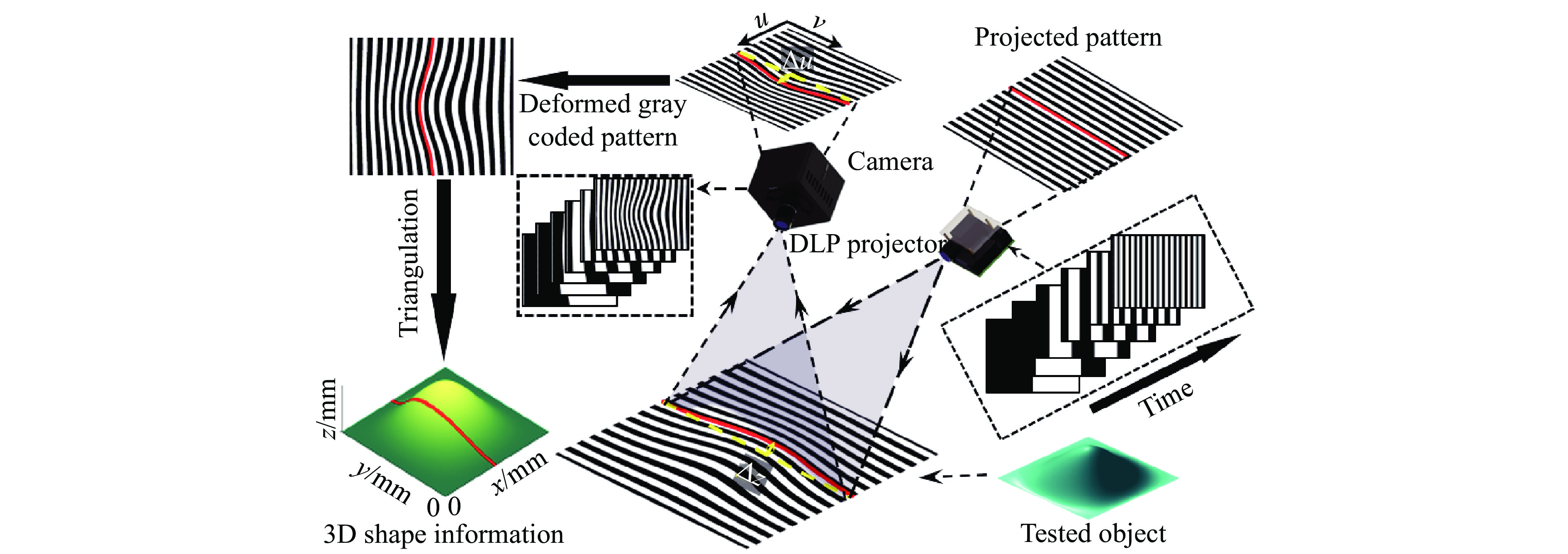
Fig. 1. Schematic diagram of 3D imaging technique based on Gray-coded structured illumination
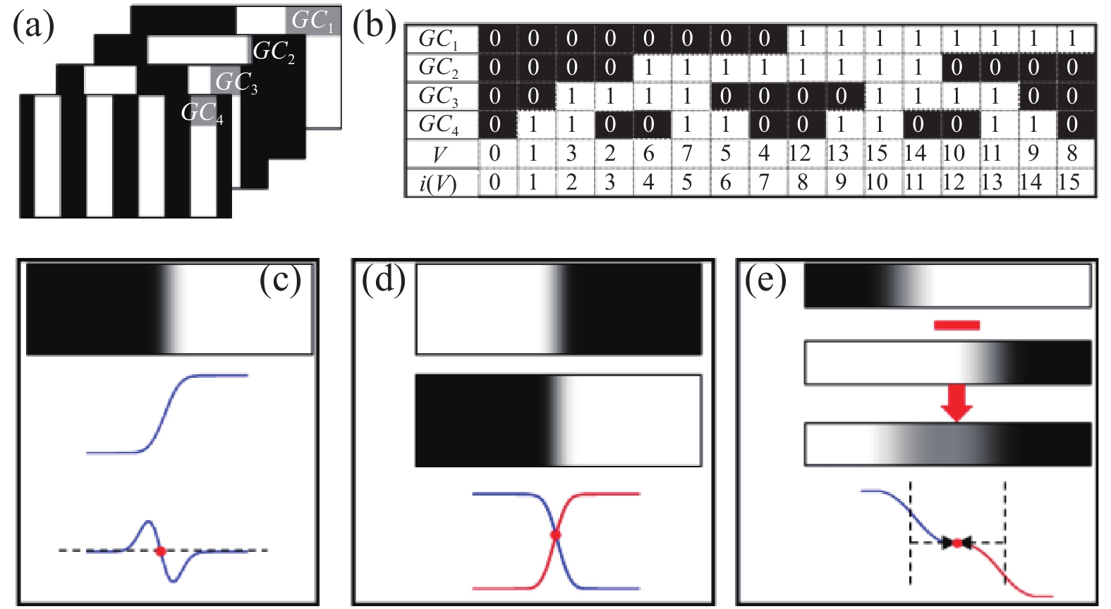
Fig. 2. Direct Gray-coded coding technique. (a) Projected patterns; (b) Decoding process of Gray code; (c) Zero-crossing edge detection method; (d) Positive and negative edge detection method; (e) Improved zero-crossing edge detection method
Fig. 3. Gray-coded-aided line shifting technique. (a) Projected line-shifting patterns; (b) Projected Gray-coded patterns; (c) Decoding process; (d) Peak detection of the line
Fig. 4. Gray-coded-aided stripe edge shifting technique. (a) Projected stripe-edge-shifting patterns; (b) Projected Gray-coded patterns; (c) Decoding process
Fig. 5. Experimental results of the Gray-coded-aided stripe edge shifting technique [36]. (a) Microchip; (b) Measuring result of a microchip; (c) Coin; (d) Measuring result of a coin
Fig. 6. Experimental results of the improved Gray-coded-aided stripe edge shifting technique [38]. (a) Captured fringe pattern with low exposure time; (b) Captured fringe pattern with high exposure time; (c) Generated fringe pattern using HDR technique; (d) Measuring result of the metal surface
Fig. 7. Gray-coded-aided phase shifting technique. (a) Projected phase-shifting patterns; (b) Projected Gray-coded patterns; (c) Decoding process
Fig. 8. Decoding process of the complementary Gray codes
Fig. 9. Experimental results of the complementary Gray-coded-aided phase shifting technique. (a) Experimental result of the traditional Gray-coded-aided phase shifting technique; (b) Partial enlargement of (a); (c) Experimental result of the complementary Gray-coded-aided phase shifting technique; (d) Partial enlargement of (c)
Fig. 10. Representative techniques of fringe binarization. (a) Binary square wave; (b) Optimal pulse width modulation; (c) Two dimensional dithering binarization
Fig. 11. Schematic diagram of the cyclic complementary Gray-coded-aided phase shifting technique
Fig. 12. Experimental results of the cyclic complementary Gray-coded-aided phase shifting technique. (a) 3D reconstruction of the impact process of Newton’s cradle; (b) Velocity change of the left and right balls in the impact process
Fig. 13. Schematic diagram of the shifting Gray-coded-aided phase shifting technique
Fig. 14. Experimental results of reconstructing the simple pendulum swing using shifting Gray-coded-aided phase shifting technique
Fig. 15. Experimental results of reconstructing the collapsing building blocks using shifting Gray-coded-aided phase shifting technique
Fig. 16. Ternary Gray-coded-aided phase shifting technique. (a) Projected ternary Gray-coded patterns; (b) Projected binarized phase-shifting patterns; (c) Decoding process of ternary Gray-code
Fig. 17. Schematic diagram of the light plane method
Fig. 18. Schematic diagram of the method based on inverse projector calibration
Fig. 19. Schematic diagram of the implicit calibration method

Set citation alerts for the article
Please enter your email address
© Copyright 2018-2021 | Chinese Laser Press. All Rights Reserved 沪ICP备15018463号-20