• Chinese Journal of Lasers
  • Vol. 50, Issue 16, 1602105 (2023)
Lanyun Qin1, Kun Wang1, Wei Wang1, Xiangming Wang2, and Guang Yang1、*
Author Affiliations
  • 1School of Mechatronic Engineering, Shenyang Aerospace University, Shenyang 110136, Liaoning, China
  • 2Shenyang Aircraft Design Institute, Aviation Industry Corporation of China, Ltd., Shenyang 110035, Liaoning, China
  • show less
    DOI: 10.3788/CJL221501 Cite this Article Set citation alerts
    Lanyun Qin, Kun Wang, Wei Wang, Xiangming Wang, Guang Yang. Warping Detection and Cracking Prediction of Laser Deposition Manufacturing[J]. Chinese Journal of Lasers, 2023, 50(16): 1602105 Copy Citation Text show less
    Roadmap of warping detection and cracking prediction system
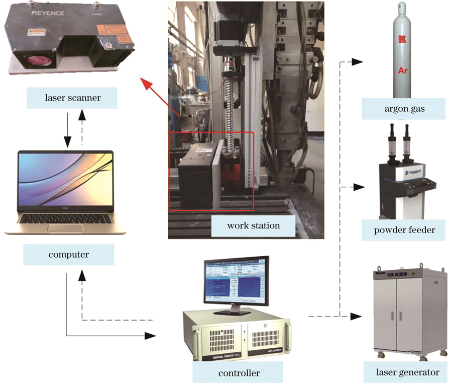
    Fig. 1. Roadmap of warping detection and cracking prediction system
    Software architecture of warping detection and cracking prediction in LDM
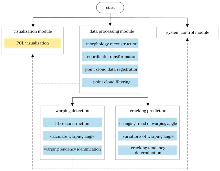
    Fig. 2. Software architecture of warping detection and cracking prediction in LDM
    Algorithm flow and detection principle. (a) Coordinate system calibration and point cloud data pre-processing flow; (b) in‐situ detection principle
    Fig. 3. Algorithm flow and detection principle. (a) Coordinate system calibration and point cloud data pre-processing flow; (b) in‐situ detection principle
    Definition of warping angle
    Fig. 4. Definition of warping angle
    Two warping detection schemes. (a) Rotary slicing planes and intersecting lines; (b) parallel slicing planes and intersecting lines; (c) rotary slicing planes and parallel slicing planes were combined
    Fig. 5. Two warping detection schemes. (a) Rotary slicing planes and intersecting lines; (b) parallel slicing planes and intersecting lines; (c) rotary slicing planes and parallel slicing planes were combined
    Algorithm flow of warping detection
    Fig. 6. Algorithm flow of warping detection
    Schematic of the variation in warping angle
    Fig. 7. Schematic of the variation in warping angle
    Cracking prediction algorithm flow
    Fig. 8. Cracking prediction algorithm flow
    Cracking affected area determined by rotary slices. (a) Rotary slices; (b) intersecting line with the largest warping angle and four nearby intersecting lines
    Fig. 9. Cracking affected area determined by rotary slices. (a) Rotary slices; (b) intersecting line with the largest warping angle and four nearby intersecting lines
    Warping detection experiment. (a) Surface warping; (b) point cloud data after pre-processing; (c) reconstructed surface; (d) obtain the intersection lines by rotary slicing planes; (e) obtain the intersection lines by parallel slicing planes
    Fig. 10. Warping detection experiment. (a) Surface warping; (b) point cloud data after pre-processing; (c) reconstructed surface; (d) obtain the intersection lines by rotary slicing planes; (e) obtain the intersection lines by parallel slicing planes
    Experiment result of cracking prediction. (a) Variation trend of Qn and K; (b) warping angle in cracking affected area at layer 51; (c) variation of warping angle at layer 51; (d) cracking at layer 55
    Fig. 11. Experiment result of cracking prediction. (a) Variation trend of Qn and K; (b) warping angle in cracking affected area at layer 51; (c) variation of warping angle at layer 51; (d) cracking at layer 55
    Numberα /(°)H /mmL /mmQ /(°)Trend of warping
    104.0468.813.36Yes
    2153.3267.202.83No
    3303.9685.592.65No
    4453.0277.672.23No
    5601.2377.210.91No
    6751.3985.620.93No
    7901.3479.780.96No
    81052.2478.791.63No
    91202.6890.331.70No
    101352.3568.321.97No
    111502.6264.112.34No
    121653.8273.982.96No
    Table 1. Calculated warping angle of intersecting lines obtained by rotary slicing planes
    NumberH /mmL /mmQ /(°)Trend of warping
    14.0468.813.36Yes
    24.1866.163.62Yes
    34.1564.883.66Yes
    214.0766.793.49Yes
    224.1465.163.64Yes
    Table 2. Warping trend detection results of the first slicing plane and four adjacent intersecting lines
    Layer numberL /mmH /mmQn /(°)K /(°)Q1 /(°)K1 /(°)
    4548.234.094.854.82
    4649.514.284.944.91
    4748.984.575.335.3
    4849.024.835.635.58
    4947.635.116.126.08
    5047.95.36.311.466.251.43
    5149.085.616.521.586.471.56
    5246.375.917.261.937.191.89
    5344.736.287.992.367.932.35
    5445.366.898.642.528.612.53
    5544.428.911.335.0211.275.02
    Layer numberQ2 /(°)K2 /(°)Q3 /(°)K3 /(°)Q4 /(°)K4 /(°)
    454.784.834.8
    464.884.934.91
    475.265.315.28
    485.535.595.55
    496.036.076.04
    506.21.426.261.436.211.41
    516.411.536.461.536.381.47
    527.131.877.21.897.121.84
    537.882.357.942.357.872.32
    548.572.548.62.538.512.47
    5511.235.0311.285.0211.194.98
    Table 3. Calculated warping angle Q and variation K in five consecutive layers at layer 45–55
    Lanyun Qin, Kun Wang, Wei Wang, Xiangming Wang, Guang Yang. Warping Detection and Cracking Prediction of Laser Deposition Manufacturing[J]. Chinese Journal of Lasers, 2023, 50(16): 1602105
    Download Citation