• Infrared and Laser Engineering
  • Vol. 50, Issue 9, 20210090 (2021)
Rui Qu1、2, Huinan Guo1, Jianzhong Cao1, and Jianfeng Yang1
Author Affiliations
  • 1Xi’an Institute of Optical and Precision Mechanics, Chinese Academy of Sciences, Xi’an 710119, China
  • 2Univisity of Chinese Academy of Sciences, Beijing 100049, China
  • show less
    DOI: 10.3788/IRLA20210090 Cite this Article
    Rui Qu, Huinan Guo, Jianzhong Cao, Jianfeng Yang. Design of visible-near infrared athermal continuous zoom optical system[J]. Infrared and Laser Engineering, 2021, 50(9): 20210090 Copy Citation Text show less
    Schematic diagram of typical two part zoom lens system
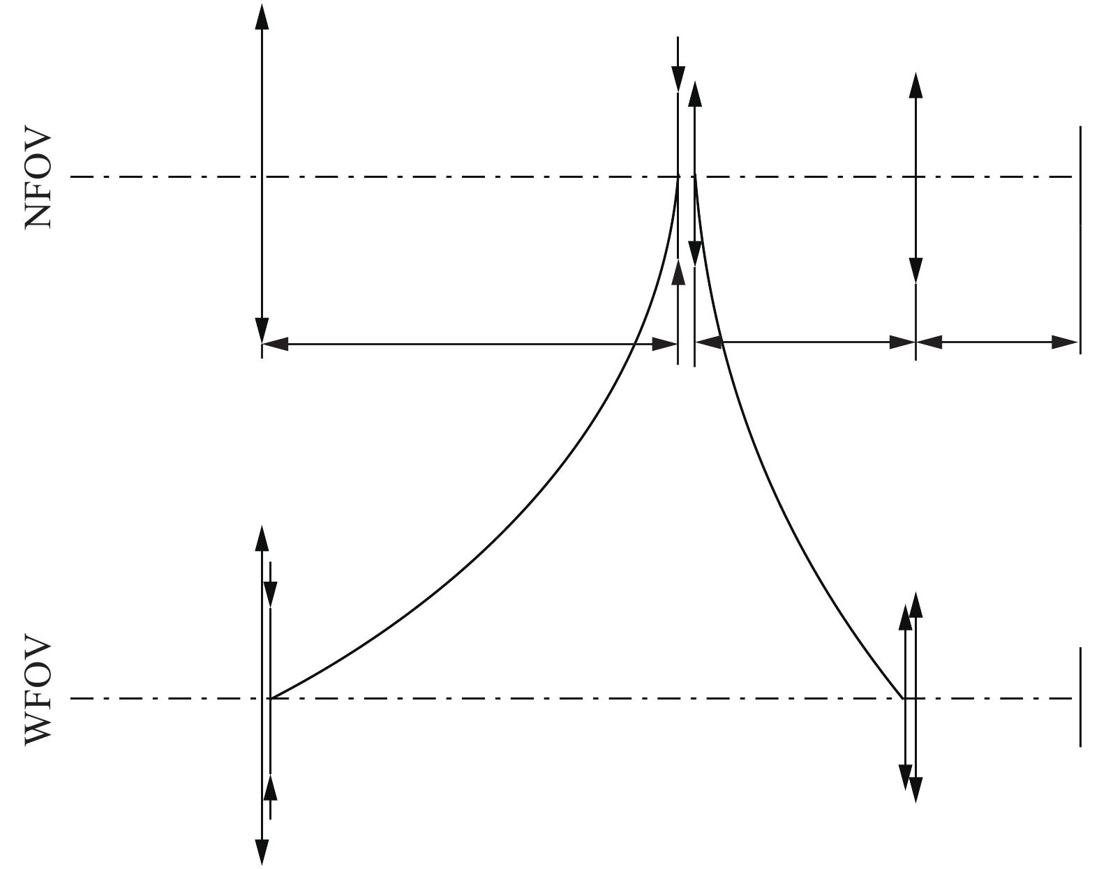
    Fig. 1. Schematic diagram of typical two part zoom lens system
    Optimization results diagram of visible-near infrared continuous zoom optical system
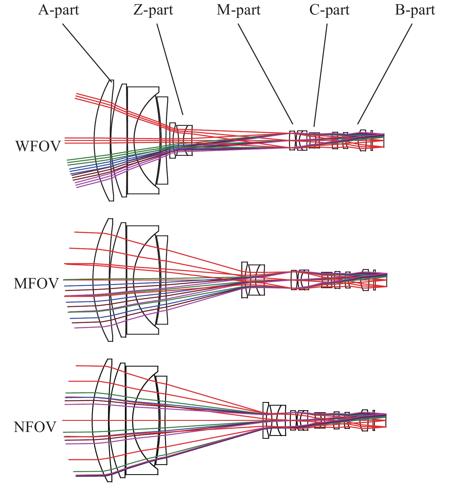
    Fig. 2. Optimization results diagram of visible-near infrared continuous zoom optical system
    Resulted cam curve of the zoom lens system
    Fig. 3. Resulted cam curve of the zoom lens system
    Cumulative probability of MTF in 0.48-0.68 μm
    Fig. 4. Cumulative probability of MTF in 0.48-0.68 μm
    ParameterValue
    Work wavelength/μm0.48-0.68 and 0.7-0.9
    Field of view (FOV)/(°)38.1×22.0-2.5×1.4
    Effective focal length/mm8-120
    F-number 5
    Overall length/mm≤90
    Back focal length/mm≥5.5
    Work temperature/℃−40-60
    Table 1. Design requirements
    −40 ℃20 ℃60 ℃
    EFL=8 mm
    EFL=70 mm
    EFL=120 mm
    Table 2. MTF of the zoom optical system in 0.48-0.68 μm at −40 ℃, 20 ℃ and 60 ℃
    −40 ℃20 ℃60 ℃
    EFL=8 mm
    EFL=70 mm
    EFL=120 mm
    Table 3. MTF of the zoom optical system in 0.7-0.9 μm at −40 ℃, 20 ℃ and 60 ℃
    Rui Qu, Huinan Guo, Jianzhong Cao, Jianfeng Yang. Design of visible-near infrared athermal continuous zoom optical system[J]. Infrared and Laser Engineering, 2021, 50(9): 20210090
    Download Citation