
Shuwen Ran, Xianming Liu, Xiaohua Lei, Peng Zhang, Shaoyun Yin. Three-Dimensional Shape Measurement of Head-Up Display Virtual Image Based on Binocular Vision[J]. Acta Optica Sinica, 2022, 42(19): 1912001
- Acta Optica Sinica
- Vol. 42, Issue 19, 1912001 (2022)
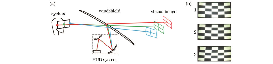
Fig. 1. Imaging of HUD system. (a) Imaging process; (b) HUD virtual image observed at different positions (1, 2, and 3 are the virtual images observed at the left, center, and right positions, respectively)
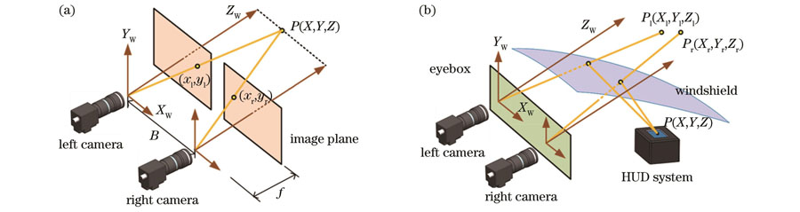
Fig. 2. Binocular measurement and binocular virtual image measurement of HUD. (a) Principle of binocular measurement; (b) binocular measurement for HUD virtual images
Fig. 3. HUD design model and simulation results. (a) Schematic diagram; (b) light trace diagram; (c) grid distortion; (d) spot diagram
Fig. 4. Virtual image coordinates simulated at different observation positions
Fig. 5. Track of virtual image center varying with observation position
Fig. 6. Simplified model of binocular measurement error caused by position change of image point
Fig. 7. Image point coordinate change and measurement error caused. (a) Change of image point; (b) measurement error
Fig. 8. Baseline systematic error and total measurement error caused by baseline change. (a) Baseline systematic error; (b) total measurement error caused by baseline change
Fig. 9. Experimental system for HUD virtual image measurement. (a) Schematic diagram of measurement system; (b) experimental setup; (c) actually projected image; (d) display virtual image [ camera is located at (-60 mm, 0 mm)]
Fig. 10. Virtual image shape measurement results. (a) Stereoscopic view; (b) side view
Fig. 11. Division of virtual image measurement results

Set citation alerts for the article
Please enter your email address
© Copyright 2018-2021 | Chinese Laser Press. All Rights Reserved 沪ICP备15018463号-20