• Acta Optica Sinica
  • Vol. 44, Issue 10, 1026026 (2024)
Yangliang Li1、2, Yunlong Wu1、2、*, Qing Ye1、2、**, Bingyan Wei3, Haoqi Luo1、2, Ke Sun1、2, Hao Zhang1、2, Wenqi Zhang4, and Xiaoquan Sun1、2
Author Affiliations
  • 1State Key Laboratory of Pulsed Power Laser Technology, National University of Defense Technology, Hefei 230037, Anhui , China
  • 2Advanced Laser Technology Laboratory of Anhui Province, Hefei 230037, Anhui , China
  • 3School of Physical Science and Technology, Northwestern Polytechnical University, Xi an 710129, Shaanxi , China
  • 4School of Noncommissioned Officers, Army Academy of Armored Forces, Changchun , 130000, Jilin , China
  • show less
    DOI: 10.3788/AOS231570 Cite this Article Set citation alerts
    Yangliang Li, Yunlong Wu, Qing Ye, Bingyan Wei, Haoqi Luo, Ke Sun, Hao Zhang, Wenqi Zhang, Xiaoquan Sun. Limit of Laser Protection Capability of Arcsine Coded Imaging System[J]. Acta Optica Sinica, 2024, 44(10): 1026026 Copy Citation Text show less
    Imaging model of wavefront coded imaging system
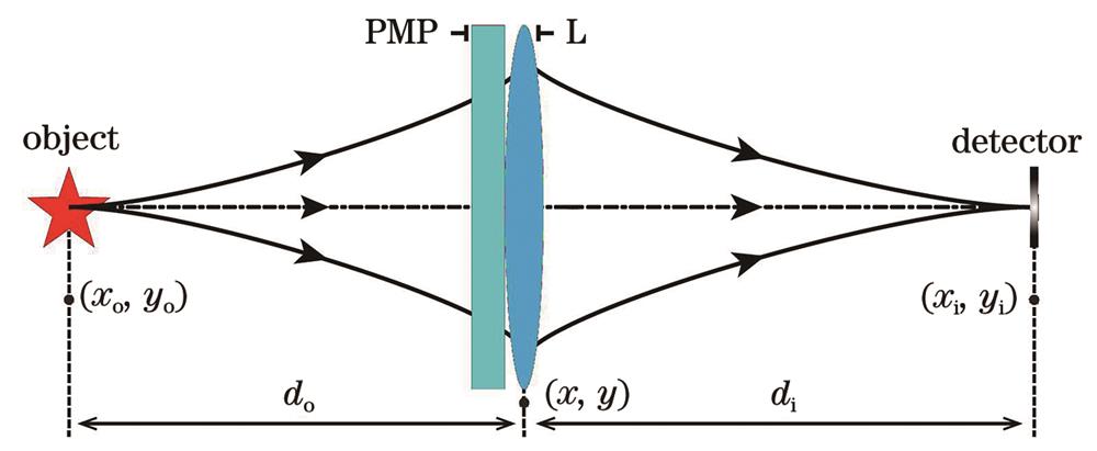
    Fig. 1. Imaging model of wavefront coded imaging system
    Comparison of imaging results between conventional imaging system and ASPM wavefront coded imaging system
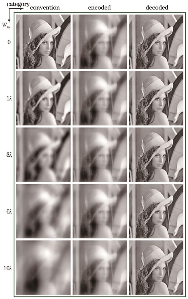
    Fig. 2. Comparison of imaging results between conventional imaging system and ASPM wavefront coded imaging system
    PSNR and SSIM curves of conventional imaging system and ASPM wavefront coded imaging system
    Fig. 3. PSNR and SSIM curves of conventional imaging system and ASPM wavefront coded imaging system
    Laser propagation model of wavefront coded imaging system
    Fig. 4. Laser propagation model of wavefront coded imaging system
    Spot profiles and corresponding maximum single-pixel receiving power with different defocus parameters at imaging plane
    Fig. 5. Spot profiles and corresponding maximum single-pixel receiving power with different defocus parameters at imaging plane
    Variation curves of maximum single-pixel receiving power with defocus parameters at imaging plane
    Fig. 6. Variation curves of maximum single-pixel receiving power with defocus parameters at imaging plane
    Echo spot profiles and corresponding echo-detection receiving power with different defocus parameters
    Fig. 7. Echo spot profiles and corresponding echo-detection receiving power with different defocus parameters
    Variation curves of echo-detection receiving power with defocus parameters
    Fig. 8. Variation curves of echo-detection receiving power with defocus parameters
    ParameterValue
    Imaging lens diameter50 mm
    Imaging lens focal length100 mm
    Object distance2000 m
    Image distance100.0 mm
    Imaging plane length0.2725 mm
    Modulation factor42.21
    Tentative parameter4.25×10-4
    Table 1. Numerical simulation parameters of imaging system
    ParameterValue
    Laser power1000 W
    Laser wavelength532 nm
    Gaussian beam waist size2.5 mm
    Propagation distance2000 m
    Imaging lens focal length100 mm
    Imaging lens sizeФ50 mm
    Imaging plane pixel size2.0 μm×2.0 μm
    Imaging plane reflectance0.1
    Echo detector sizeФ25 mm
    Table 2. Numerical simulation parameters of laser propagation model
    Yangliang Li, Yunlong Wu, Qing Ye, Bingyan Wei, Haoqi Luo, Ke Sun, Hao Zhang, Wenqi Zhang, Xiaoquan Sun. Limit of Laser Protection Capability of Arcsine Coded Imaging System[J]. Acta Optica Sinica, 2024, 44(10): 1026026
    Download Citation