• Photonics Research
  • Vol. 6, Issue 6, 542 (2018)
Juliane Eggert, Bjoern Bourdon, Stefan Nolte, Joerg Rischmueller, and Mirco Imlau*
Author Affiliations
  • School of Physics, Osnabrück University, Barbarastr. 7, 49076 Osnabrück, Germany
  • show less
    DOI: 10.1364/PRJ.6.000542 Cite this Article Set citation alerts
    Juliane Eggert, Bjoern Bourdon, Stefan Nolte, Joerg Rischmueller, Mirco Imlau. Chirp control of femtosecond-pulse scattering from drag-reducing surface-relief gratings[J]. Photonics Research, 2018, 6(6): 542 Copy Citation Text show less
    (a) Scanning electron microscope (SEM) image and schematic, three-dimensional representation of the riblet structure under study. (b) Scheme of the optical setup of the riblet sensor described in Refs. [8,9]: the laser beam is incident normal to the riblet sample’s surface, and the intensity distribution of the scattered light is detected in the 0° and ±45° directions. Degradation of the riblet structure is measured as a decrease in intensity around 45°. D1–D3, Si-PIN-diodes; BS, beam-splitter; M1, M2, mirrors; TS1–TS3, motorized translation stages.
    Fig. 1. (a) Scanning electron microscope (SEM) image and schematic, three-dimensional representation of the riblet structure under study. (b) Scheme of the optical setup of the riblet sensor described in Refs. [8,9]: the laser beam is incident normal to the riblet sample’s surface, and the intensity distribution of the scattered light is detected in the 0° and ±45° directions. Degradation of the riblet structure is measured as a decrease in intensity around 45°. D1–D3, Si-PIN-diodes; BS, beam-splitter; M1, M2, mirrors; TS1–TS3, motorized translation stages.
    (a) Scheme of the pulse front reflected in the 45° direction and distinct pulse path lengths from next-neighboring riblet flanks. Period Λ of the riblet structure is 100 μm, and riblet height h is 50 μm. The spatial delay induced by the riblet structure is 70 μm, and the correlated temporal delay is about Δt=230 fs. (b) and (c) are discussed in the simulation section.
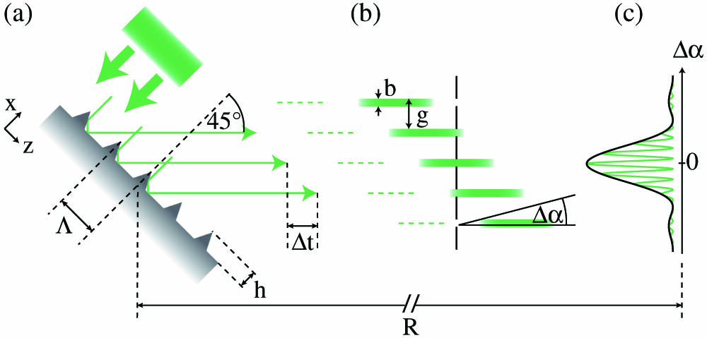
    Fig. 2. (a) Scheme of the pulse front reflected in the 45° direction and distinct pulse path lengths from next-neighboring riblet flanks. Period Λ of the riblet structure is 100 μm, and riblet height h is 50 μm. The spatial delay induced by the riblet structure is 70 μm, and the correlated temporal delay is about Δt=230  fs. (b) and (c) are discussed in the simulation section.
    (a) First setup: the laser beam is incident via mirrors M1–M3 normal to the riblet sample’s surface and the scattered intensity pattern is observed on a screen or detected via a photodiode array in the 45° direction. The initial pulse duration is τ=109 fs. In order to expand the pulse duration, blocks of borosilicate crown glass are placed into the beam path. (b) Second setup: the laser beam is adjusted into a grating stretcher built of BG1, BG2, and M4. Distance between the two blazed gratings of 176(1) cm results in τ2=2.4 ps. The variable slit VS allows for a limitation of the effective bandwidth Δω of the laser pulse. Its aperture a is varied from 1 to 7 mm. The D-shaped mirror DM separates incoming and stretched pulses. P1–P3 are pinholes to eliminate scattering.
    Fig. 3. (a) First setup: the laser beam is incident via mirrors M1–M3 normal to the riblet sample’s surface and the scattered intensity pattern is observed on a screen or detected via a photodiode array in the 45° direction. The initial pulse duration is τ=109  fs. In order to expand the pulse duration, blocks of borosilicate crown glass are placed into the beam path. (b) Second setup: the laser beam is adjusted into a grating stretcher built of BG1, BG2, and M4. Distance between the two blazed gratings of 176(1) cm results in τ2=2.4  ps. The variable slit VS allows for a limitation of the effective bandwidth Δω of the laser pulse. Its aperture a is varied from 1 to 7 mm. The D-shaped mirror DM separates incoming and stretched pulses. P1–P3 are pinholes to eliminate scattering.
    (a) Intensity patterns of the 45° signal obtained with the first setup for pulse durations of (1) 109 fs, (2) 234 fs, (3) 370 fs, (4) 680 fs, and (5) 900 fs, respectively. (b)–(e) Photographs of the intensity patterns (b), (c) at 900 fs and (d), (e) with a continuous-wave laser (λ=532 nm). (b) The 45° signal appears smoothly. This finding is in contrast to the observable substructure of the 45° signal well-known from continuous wave-experiments shown in (d). (c), (e) In 0° direction, both intensity patterns show distinct interference features with three prominent center peaks.
    Fig. 4. (a) Intensity patterns of the 45° signal obtained with the first setup for pulse durations of (1) 109 fs, (2) 234 fs, (3) 370 fs, (4) 680 fs, and (5) 900 fs, respectively. (b)–(e) Photographs of the intensity patterns (b), (c) at 900 fs and (d), (e) with a continuous-wave laser (λ=532  nm). (b) The 45° signal appears smoothly. This finding is in contrast to the observable substructure of the 45° signal well-known from continuous wave-experiments shown in (d). (c), (e) In 0° direction, both intensity patterns show distinct interference features with three prominent center peaks.
    Intensity pattern as a function of slit aperture a and accordingly labeled from 1 to 7. Smooth intensity distribution for a=7 mm as found in Fig. 4(a). With decreasing slit aperture and consequently decreasing pulse duration and bandwidth, the interference pattern appears. The results of the detected intensity patterns for a=1 mm and a=7 mm are fitted to the sum of two Gaussian functions. On the right, the respective visibilities ν are specified.
    Fig. 5. Intensity pattern as a function of slit aperture a and accordingly labeled from 1 to 7. Smooth intensity distribution for a=7  mm as found in Fig. 4(a). With decreasing slit aperture and consequently decreasing pulse duration and bandwidth, the interference pattern appears. The results of the detected intensity patterns for a=1  mm and a=7  mm are fitted to the sum of two Gaussian functions. On the right, the respective visibilities ν are specified.
    Numeric energy pattern W(Δα) for 45° (a) for a constant bandwidth of Δω=3.41×10¹³ rad/s (Δλ=4.8 nm) and variable pulse duration τ and frequency gradient ∂ω/∂t, and (b) for a constant frequency gradient ∂ω/∂t=1.49×1025 rad/s2 and variable pulse duration τ and bandwidth Δω (N=13, M=5, b=15 μm, Λ=100 μm, R=0.36 m).
    Fig. 6. Numeric energy pattern W(Δα) for 45° (a) for a constant bandwidth of Δω=3.41×10¹³  rad/s (Δλ=4.8  nm) and variable pulse duration τ and frequency gradient ω/t, and (b) for a constant frequency gradient ω/t=1.49×1025  rad/s2 and variable pulse duration τ and bandwidth Δω (N=13, M=5, b=15  μm, Λ=100  μm, R=0.36  m).
    Plot of frequency ω and power P versus time for two next-neighboring pulses with a mutual temporal delay of 230 fs. Slope of frequency is ∂ω/∂t=Δω/τ. (a) Frequency detuning Ωa for overlapping pulses. (b) Same pulse duration as in (a), while bandwidth is decreased, which results in the appearance of a stationary interference pattern.
    Fig. 7. Plot of frequency ω and power P versus time for two next-neighboring pulses with a mutual temporal delay of 230 fs. Slope of frequency is ω/t=Δω/τ. (a) Frequency detuning Ωa for overlapping pulses. (b) Same pulse duration as in (a), while bandwidth is decreased, which results in the appearance of a stationary interference pattern.
    Influence of structure period Λ on threshold values of (a) pulse duration τ and (b) bandwidth Δω for a vanishing interference pattern (ν<0.1). Characteristic period Λ=100 μm of the investigated riblet structure is marked, respectively.
    Fig. 8. Influence of structure period Λ on threshold values of (a) pulse duration τ and (b) bandwidth Δω for a vanishing interference pattern (ν<0.1). Characteristic period Λ=100  μm of the investigated riblet structure is marked, respectively.
    Slit Aperturea (mm)Pulse Durationτ (ps)Spectral BandwidthΔω (rad/s)Ωτ
    7.0(1)2.40(10)3.56×10138.18
    6.0(1)2.30(10)3.56×10138.18
    5.0(1)2.25(10)2.85×10136.55
    4.0(1)2.00(10)2.35×10135.40
    3.0(1)1.70(10)2.42×10135.56
    2.0(1)1.25(20)2.06×10134.75
    1.0(1)0.90(20)1.92×10134.42
    Table 1. Slit Apertures a, Pulse Duration τ, and Spectral Bandwidth Δωa
    Juliane Eggert, Bjoern Bourdon, Stefan Nolte, Joerg Rischmueller, Mirco Imlau. Chirp control of femtosecond-pulse scattering from drag-reducing surface-relief gratings[J]. Photonics Research, 2018, 6(6): 542
    Download Citation