Modal analysis of the highly efficient reflective triangular grating operating in the 800 nm wavelength under normal incidence for TE polarization is presented in this Letter. The rigorous coupled wave analysis and simulated annealing algorithm are used to design this beam splitter. The reflective grating consists of a highly reflective mirror and a transmission grating on the top. The mechanism of the reflective triangular grating is clarified by the simplified modal method. Then, gratings are fabricated by direct laser writing lithography.
In a high-power laser system, reflective gratings with high efficiency are needed[1]. Reflective gratings are also used in various fields, such as beam combining, pulse compression[2], infrared spectroscopy[3], and femtosecond lasers[4]. Metal dielectric reflection gratings as three-channel beam splitters can be widely used in optical systems of holography and interferometers[5]. The beam splitters are key elements and have been widely researched and used[6,7]. However, conventional beam splitter gratings, such as Dammann gratings[8], have some disadvantages, including low efficiency. The efficiency of traditional Dammann gratings is about 75%[9]. Such an efficiency is not high enough to meet the high-efficiency requirement of high-power laser systems. Hence, subwavelength Dammann gratings with higher efficiencies should be taken into consideration.
The Dammann grating is designed and optimized by the rigorous coupled wave analysis (RCWA)[10] and simulated annealing (SA) algorithm[11,12]. SA is a probabilistic technique that can approximate the global optimum of a given function. However, the RCWA is a purely numerical method, and it seems difficult to know the mechanism of triangular gratings by only using a numerical method. Therefore, for further understanding, we use the simplified modal method to explain the interference process in this grating. The modal method was first developed by Rytov and Collin[13,14], and it was Botten et al.[15] who first applied it to dielectric gratings. The simplified modal method has been used to clarify the mechanisms of different gratings[16–22]. Zheng et al. analyzed the transmission of triangular-groove gratings by the simplified modal method[17]. The expression of transmission the Dammann grating under normal incidence has also been derived by the simplified modal method[18]. But this expression is not suitable for reflective gratings. Reflective gratings have only been analyzed in a Littrow mounting[21,22] with the simplified modal method by Hu et al. In addition, as we know, this method has already been applied to analyze beam splitting gratings under the second Bragg incidence[20]. However, a simplified modal analysis of reflective triangular gratings under normal incidence has not been done before to the best of our knowledge.
In this Letter, the metal-mirror-based reflective grating consists of a highly reflective mirror and a transmission grating on the top. By using the grating modes and ignoring the absorption of the mirror and the evanescent wave, the expressions for the diffraction efficiency of the reflective grating can be derived. The diffraction efficiency of the optimized grating is higher than 98% at the wavelength of 800 nm, and these Dammann gratings are fabricated by direct laser writing (DLW) lithography.
Sign up for Chinese Optics Letters TOC. Get the latest issue of Chinese Optics Letters delivered right to you!Sign up now
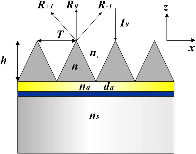
Figure 1 is the schematic of this reflective triangular grating for TE polarization under normal incidence; it is composed of a grating layer (depth and index ), a thin gold layer (depth and index ), and a fused-silica substrate (index ). represents the period of the grating, and is the refractive index of the incident medium, which is in air.
This kind of grating is similar to a gold grating. Hence, the threshold of it is about in a high-power laser system[23]. The RCWA in association with the SA algorithm is adopted to calculate and optimize this structure. The set is chosen as the optimization parameters. The merit function (MF) is where is the reflective efficiency of the th order calculated by the RCWA, and is the average value of the efficiencies of the three orders. is the number of wavelength points from 780 to 820 nm.
The RCWA and SA algorithm are used to make the minimization subject to MF. The smaller the value of MF is, the closer the iteration point is to the optimal parameter. After optimization, we obtained the optimal value [1290, 558]. The unit is nanometer. The MF with optimal values may not be the global minimum. But the efficiency and uniformity of the designed gratings with the optimal values can meet our requirements. The efficiencies of the zeroth order and the first order are 32.24% and 33.21% in theory.
Figure 2 shows the efficiencies of the zeroth and first orders for TE polarization versus the wavelength under normal incidence. The efficiencies of the st are equal under normal incidence. From 780 to 820 nm, the efficiencies are all above 30%. Especially around the wavelength of 800 nm, the efficiencies of the three orders are nearly equal, which demonstrates the good ability of the beam splitting.
Figure 2.Diffraction efficiencies of the zeroth and first orders.
The efficiency and uniformity will change if the groove depth or period deviates from the optimized values. Figure 3 shows the contour of the ratio of efficiency of the first order and zeroth order versus the period and depth . From Fig. 3, it can be seen that the ratio can be nearly equal to 1 and the gratings can be done with a period ranging from 1200 to 1300 nm and a depth ranging from 480 to 620 nm. Hence, around wavelength 800 nm, there is a large tolerance, which provides convenience for fabrication.
Figure 3.Contour of the efficiency ratio between the first and the zeroth diffractive orders versus the period and depth.
For further understanding, we use the simplified modal method to explain the interference process in this grating. According to the simplified modal method, when the period of a grating is of the order of the wavelength, the diffraction of the grating could be predicted by a few propagating grating modes. Since the contrast of the refractive indices is low (), the modes of the gratings can be regarded as propagating independently. For a triangular grating, it can be approximated by a stack of lamellar gratings. Compared to the Littrow incidence, the expression of efficiencies of zeroth and st orders are more complicated for TE polarization under normal incidence.
The effective indices of every lamellar grating can be found by solving the following eigenfunction equation for TE polarization: with and , with incidence angle and the wavenumber in a vacuum. For this triangular-groove grating, the duty cycle goes from 0 (top) to 1 (bottom). The average mode indices of mode 0, mode 1, and mode 2 are shown as follows: where is the depth of the th lamellar grating, and , , and are the effective indices of mode 0, mode 1, and mode 2 of the corresponding layer. Hence, we can obtain the average mode indices of mode 0, mode 1, and mode 2 with a period of 1290 nm and a wavelength of 800 nm, and they are equal to 1.48733, 1.24690, and 1.08297, respectively.
A reflective grating consists of a transmission grating and a highly reflective mirror. The propagating and diffraction in the grating are shown in Fig. 4. When the reflective grating is illuminated under normal incidence, firstly, three transmission diffractive orders occur. , , and represent the diffractive orders of the first diffraction.
Figure 4.Diffraction process of the metal-mirror-based reflective grating.
According to the diffraction under normal incidence[18], the complex amplitudes of three orders can be derived as where can be derived from the overlap integral, and is the electric field of mode (), with and .
Then, the diffractive orders are reflected back by the Au layer and diffracted again by the grating with nine diffraction waves denoted by 1 to 9. According to the grating equation, the zeroth order diffracts again under normal incidence, while the st orders diffract again under the second Bragg incidence. Hence, the expressions of the complex amplitudes of the second diffraction under normal incidence are the same as Eqs. (8) and (9), and the others are derived from the diffraction under the second Bragg incidence. The modal method analysis has been done under the second Bragg incidence[20]; therefore, the complex amplitudes of the three orders can be written as
So, considering twice diffraction, the complex amplitudes of the nine diffraction waves can be obtained, where is from 1 to 9. The expressions are shown as follows: , , , , , , , , and , where is the phase difference.
The interference between diffraction waves , , and will determine the diffraction efficiency of the positive first order of this reflective grating, and that between diffraction waves , , and determines the diffraction efficiency of the zeroth order. The negative first order is decided by , , and . Hence, the total complex amplitudes of this reflective grating are , , and . The efficiency can be obtained using
In this Letter, a beam splitter is designed, where is required. Therefore, for a splitting triangular grating with period of 1290 nm operating in the 800 nm wavelength under normal incidence, the depth can be obtained using Eqs. (8) to (14) and is equal to 533 nm approximately when neglecting the evanescent wave.
The gratings can be made on a photoresist by the lithography technique[24,25]. We have already built a DLW lithography system based on a Dammann grating[26–30]; it has the advantages of being low cost, having low requirements for the environment, and having a high flexibility. A DLW system based on a rotating Dammann grating is shown in Fig. 5.
The method of the rotating Dammann grating is a more flexible way and can improve the precision of the period. The period of designed grating is where is the initial period based on the Dammann grating, and is the rotation angle. In this setup, a Dammann grating is applied. According to the design of whole system, the initial period is 1861.68 nm. Therefore, the rotation angle is about 46.01°.
The triangular grating is written directly on the photoresist mask. Figure 6 is the angular spectrum that shows the theoretical efficiency with optimal parameters and experimental values of the st order and the zeroth order for different incident angles at the wavelength of 800 nm for TE polarization.
The experimental values basically agree with the theoretical values. Figure 7 is the atomic force microscopy (AFM) results of the fabricated grating. From the AFM results, the measured values of the period and depth are 1295 and 529 nm. The structure is similar to a triangle, which is consistent with the theoretical design. The efficiency of this fabricated beam splitter can reach approximately 88%.
Figure 7.AFM results: (a) AFM image, and (b) the profile along the line in (a).
There are differences between the measured results and the optimal values. The uncertainties associated with the experimental results are the measurement errors, the writing lithography errors, and the processing technology. Another important factor is that the groove structure approximates to the triangular structure because the distribution of the energy of the laser spot is a Gaussian distribution. Hence, the deviations of the grating period and the groove depth from the optimal parameters as well as the deviation of the grating profile from the standard triangular groove can all influence the efficiency. In addition, the slight roughness of the grating surface may also decrease the efficiency. Most uncertainties are not quantified. The difference between the about 98% design efficiency and the 88% experimental efficiency falls within the experimental uncertainty.
In conclusion, we analyze and fabricate a reflective triangular Dammann grating operating in the 800 nm wavelength under normal incidence for TE polarization with a high efficiency of more than 98%. Based on the former simplified modal analysis, the mechanism of the reflective triangular Dammann grating is presented in this Letter. The simplified modal method gives a brief explanation from the aspect of physics mainly. We offer the guidelines for the design of a beam splitter grating. The experimental efficiency of this beam splitter is about 88%.