• Photonics Research
  • Vol. 7, Issue 6, 615 (2019)
C. Lacava1、*, T. Dominguez Bucio1, A. Z. Khokhar1, P. Horak1, Y. Jung1, F. Y. Gardes1, D. J. Richardson1, P. Petropoulos1, and F. Parmigiani1、2
Author Affiliations
  • 1Optoelectronics Research Centre, University of Southampton, SO17 1BJ, Southampton, UK
  • 2Currently at Microsoft Research UK, CB1 2FB, Cambridge, UK
  • show less
    DOI: 10.1364/PRJ.7.000615 Cite this Article Set citation alerts
    C. Lacava, T. Dominguez Bucio, A. Z. Khokhar, P. Horak, Y. Jung, F. Y. Gardes, D. J. Richardson, P. Petropoulos, F. Parmigiani. Intermodal frequency generation in silicon-rich silicon nitride waveguides[J]. Photonics Research, 2019, 7(6): 615 Copy Citation Text show less
    (Top panel) Dual-pump Bragg scattering operation principle. When two pumps (P1 and P2) and a signal (S) are injected in third-order nonlinear media, Bragg scattering can occur if the phase matching condition is satisfied. Photons are scattered from the signal (S) to two idlers (IBS,r and IBS,b), and energy exchange also occurs between the two pumps (P1 and P2). This mechanism can be employed to realize wavelength conversion and wavelength exchange functionalities. (Bottom panel) Graph illustrating the phase matching mechanism between spatial modes in a multimode waveguide. If the two pumps (P1 and P2) are placed in the first-order mode (mode 0) and the signal and idlers in the second-order mode (mode 1), the phase matching condition can be realized and retained if a horizontal line that crosses the inverse group velocity (IGV) curves of the two considered modes can be drawn, intercepting the average frequencies of the two pumps and the signal and one idler [either IBS,r or IBS,b (yellow dots in the figure)].
    Fig. 1. (Top panel) Dual-pump Bragg scattering operation principle. When two pumps (P1 and P2) and a signal (S) are injected in third-order nonlinear media, Bragg scattering can occur if the phase matching condition is satisfied. Photons are scattered from the signal (S) to two idlers (IBS,r and IBS,b), and energy exchange also occurs between the two pumps (P1 and P2). This mechanism can be employed to realize wavelength conversion and wavelength exchange functionalities. (Bottom panel) Graph illustrating the phase matching mechanism between spatial modes in a multimode waveguide. If the two pumps (P1 and P2) are placed in the first-order mode (mode 0) and the signal and idlers in the second-order mode (mode 1), the phase matching condition can be realized and retained if a horizontal line that crosses the inverse group velocity (IGV) curves of the two considered modes can be drawn, intercepting the average frequencies of the two pumps and the signal and one idler [either IBS,r or IBS,b (yellow dots in the figure)].
    Calculated group index for the first two waveguide modes (dots, simulations based on the measured refractive index of the silicon-rich silicon nitride material; line, polynomial fit). Inset: cross-section of the silicon-rich silicon nitride waveguide (not to scale).
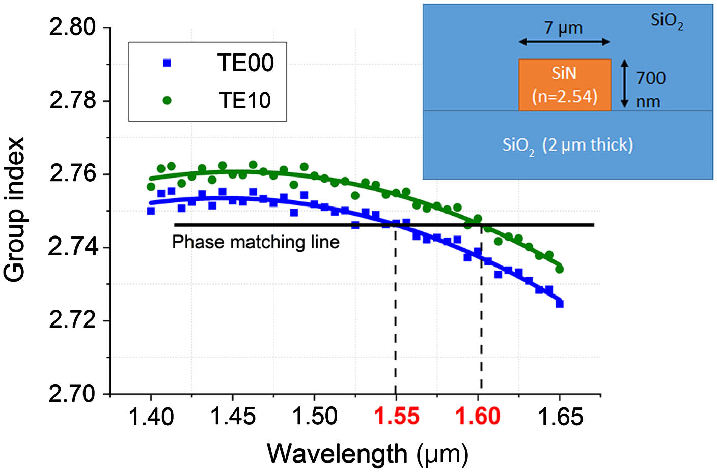
    Fig. 2. Calculated group index for the first two waveguide modes (dots, simulations based on the measured refractive index of the silicon-rich silicon nitride material; line, polynomial fit). Inset: cross-section of the silicon-rich silicon nitride waveguide (not to scale).
    Calculated BS-IM-FWM normalized efficiency for different pump-to-pump and pump-to-signal detuning values for (a) IBS,b and (b) IBS,r. Numerical results showed that phase matching can be retained for high pump-to-pump detuning values. For instance, if pump 1 (P1) is kept fixed and the second pump (P2) is detuned to a longer wavelength, the phase matching bandwidth is more than 60 nm for the IBS,r idler (see right panel), while it is significantly shorter for the IBS,b idler (see left panel). It is worth noting that opposite results would be achieved if P2 was kept constant, and P1 moved to shorter wavelength values. (c) Numerical results for a specific value of signal detuning (-5 nm from the phase matched wavelength) for the BS,b (blue line) and BS,r (red line) idlers.
    Fig. 3. Calculated BS-IM-FWM normalized efficiency for different pump-to-pump and pump-to-signal detuning values for (a) IBS,b and (b) IBS,r. Numerical results showed that phase matching can be retained for high pump-to-pump detuning values. For instance, if pump 1 (P1) is kept fixed and the second pump (P2) is detuned to a longer wavelength, the phase matching bandwidth is more than 60 nm for the IBS,r idler (see right panel), while it is significantly shorter for the IBS,b idler (see left panel). It is worth noting that opposite results would be achieved if P2 was kept constant, and P1 moved to shorter wavelength values. (c) Numerical results for a specific value of signal detuning (-5 nm from the phase matched wavelength) for the BS,b (blue line) and BS,r (red line) idlers.
    Experimental set-up. TLS: tunable laser source. OA: optical amplifier. PC: polarization controller. BS: beam splitter. PBS: polarization beam splitter. PP: phase plate. SiN-WG: silicon-rich silicon nitride waveguide.
    Fig. 4. Experimental set-up. TLS: tunable laser source. OA: optical amplifier. PC: polarization controller. BS: beam splitter. PBS: polarization beam splitter. PP: phase plate. SiN-WG: silicon-rich silicon nitride waveguide.
    Recorded spectra at (a) the TE00 port, when P1 and P2 were launched in the TE00 mode, while S was launched in the TE10 mode; (b) the TE10 port, when P1 and P2 were launched in the TE00 mode, while S was launched in the TE10 mode; and (c) the TE00 port, when all waves were launched in the TE00 mode (i.e., no intermodal FWM).
    Fig. 5. Recorded spectra at (a) the TE00 port, when P1 and P2 were launched in the TE00 mode, while S was launched in the TE10 mode; (b) the TE10 port, when P1 and P2 were launched in the TE00 mode, while S was launched in the TE10 mode; and (c) the TE00 port, when all waves were launched in the TE00 mode (i.e., no intermodal FWM).
    (a) FWM efficiency measured for different pump-to-pump detuning values for the IM scheme (red and blue squares) and for the intramodal scheme (magenta stars); (b) IM-FWM efficiency as a function of the signal wavelength (pump power 32 dBm) for IBS,r and IBS,b when the pump-to-pump detuning was 1 nm (red and blue squares, respectively) and for IBS,r when the pump-to-pump detuning was 30 nm (green squares). The inset shows a zoom-in of the plot in the region of perfect phase matching.
    Fig. 6. (a) FWM efficiency measured for different pump-to-pump detuning values for the IM scheme (red and blue squares) and for the intramodal scheme (magenta stars); (b) IM-FWM efficiency as a function of the signal wavelength (pump power 32 dBm) for IBS,r and IBS,b when the pump-to-pump detuning was 1 nm (red and blue squares, respectively) and for IBS,r when the pump-to-pump detuning was 30 nm (green squares). The inset shows a zoom-in of the plot in the region of perfect phase matching.
    C. Lacava, T. Dominguez Bucio, A. Z. Khokhar, P. Horak, Y. Jung, F. Y. Gardes, D. J. Richardson, P. Petropoulos, F. Parmigiani. Intermodal frequency generation in silicon-rich silicon nitride waveguides[J]. Photonics Research, 2019, 7(6): 615
    Download Citation