
Jianli Shang, Juntao Wang, Wanjing Peng, Hang Liu, Dan Wang, Yi Ma, Bo Fu, Yi Yu, Yujun Feng, Li Zhang, Xu Ruan, Quanwei Jin, Jiayu Yi, Xianlin Ye, Yinhong Sun, Weiping Wang, Qingsong Gao. Research progress and prospects of laser diode pumped high-energy laser[J]. High Power Laser and Particle Beams, 2022, 34(1): 011007
- High Power Laser and Particle Beams
- Vol. 34, Issue 1, 011007 (2022)
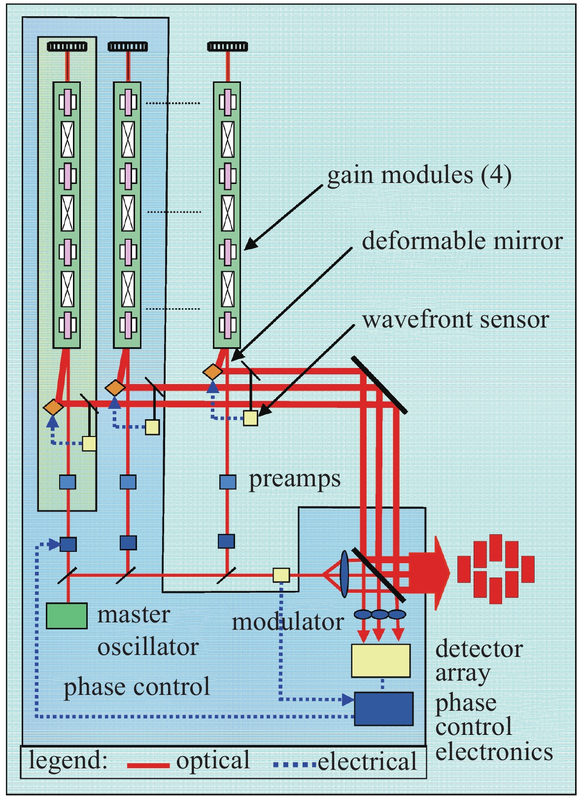
Fig. 1. Schematic diagram of 105 kW laser of Northrop Grumman

Fig. 2. Schematic diagram of the composite cooling large surface pump slats of TIPC-CAS
Fig. 3. Schematic diagram of end-pumped slab laser with conduction cooling structure
Fig. 4. Schematic diagram of end-pumped YAG slab laser with MOPA structure of CAEP
Fig. 5. 30 kW laser design concept of Raytheon
Fig. 6. 10 kW planar waveguide laser of CAEP
Fig. 7. Packaging evolution from the laboratory demonstration unit, to the optimized 100 kW head
Fig. 8. Direct liquid-cooled ThinZag laser of Textron
Fig. 9. Direct liquid-cooled thin-disk array laser of General Atomics
Fig. 10. Diagram of experimental setup of laser system of SIOM of CAS
Fig. 11. Experimental setup of 3.1 kW narrow linewidth fiber amplifier based on PRBS phase-modulated seed of MIT
Fig. 12. Scheme of the 3.25 kW all-fiber PM amplifier based on WNS phase-modulated seed of CAEP
Fig. 13. Experiments results of the 3.25 kW all-fiber PM amplifier based on WNS phase-modulated seed of CAEP
Fig. 14. Experimental setup of fiber laser combining system of Lincoln Laboratory
Fig. 15. Schematic of DOE common aperture coherent combining system of AFRL
Fig. 16. Spectrum of the SBC output beam at 30 kW of Lockheed Martin
Fig. 17. 14 kW rubidium laser output at Lawrence Livermore National Laboratory
Fig. 18. The 420 W green laser of Coherent
Fig. 19. Light path schematic diagram of green pulsed laser of TRUMPF
Fig. 20. Light path schematic diagram of 170 W extra-cavity frequency doubled green laser
Fig. 21. Slab green laser with MOPA structure(536 mJ@1 kHz)
Fig. 22. Light path schematic diagram of 550W green laser of IPG Photonics
Fig. 23. Light path schematic diagram of Yb:YAG thin slab chirped regenerative amplifier
Fig. 24. Light path schematic diagram of Yb:YAG thin slab multi-pass amplifier
Fig. 25. Schematic diagram of Yb:YAG single crystal fiber ps laser
Fig. 26. Schematic diagram of the DAPKL laser
Fig. 27. Gain module structure of Mercury
Fig. 28. Actual gain module structure of Lucia
Fig. 29. Distributed activated mirror structure laser
|
Table 1. Comparison of parameters about direct liquid cooling laser
| ||||||||||||||||||||||||||||||||||||||||||||||||||||||||||||||||||||||||
Table 2. Parameters of potassium, rubidium and cesium vapor lasers

Set citation alerts for the article
Please enter your email address
© Copyright 2018-2021 | Chinese Laser Press. All Rights Reserved 沪ICP备15018463号-20