
Xisheng Xiao, Qinghua Yu, Zhentao Zhu, Kai Hu, Guilin Chen. Encoding method of CGH for highly accurate optical measurement based on non-maxima suppression[J]. Chinese Optics Letters, 2017, 15(11): 111201
- Chinese Optics Letters
- Vol. 15, Issue 11, 111201 (2017)
Abstract
A computer-generated hologram (CGH) can generate any desired wave-front phase with diffractive light, which provides new methods for solving the problems of highly accurate optical measurement, especially in measuring complex optical surfaces[
The procedure of making a CGH includes optical design, encoding, and fabrication. The optical design can be completed using commercial optical software, and the fabrication can be completed using microelectronic technology, such as e-beam writing or laser direct writing. The encoding process can only be done by the CGH designer alone because no general method of CGH encoding is available. Most CGH studies focused on the optical design and fabrication and seldom introduced the encoding method.
The CGH-encoding process converts the desired wave-front phase function into encoded data. The format of the encoded data should be acceptable by the e-beam writing or laser direct writing machines, such as GDSII, the Caltech Intermediate Format (CIF), and the drawing exchange format (DXF)[
Sign up for Chinese Optics Letters TOC. Get the latest issue of Chinese Optics Letters delivered right to you!Sign up now
To reduce the encoding data size while obtaining high encoding accuracy, a general encoding method of applying non-maxima suppression into the process of encoding smooth CGH fringes is introduced in this Letter. In addition, the error estimate of the method is presented. On the basis of the estimation, a self-aligned CGH is designed and fabricated to verify the accuracy of the encoding method. The experimental result is given at the end of this Letter.
After the optical design, the function of the wave-front phase generated by the CGH is expressed as
![]()
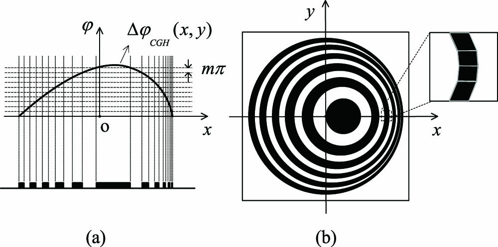
Figure 1.CGH-encoding process. (a) Generating binary fringes using phase contour interferograms. (b) Encoding the fringes into polygons.
The CGH-encoding process inevitably introduces error to the wave-front, because any deviation from the ideal fringes leads to a wave-front phase error[
![]()
Figure 2.Deviations introduced by encoding.
The wave-front phase error generated by the deviation is expressed as[
Obviously, encoding using shorter segments could reduce the encoding error. In this case, more segments are needed, and the number of vertices grows. To encode smooth CGH fringes with fewer vertices while minimizing the encoding error, the vertices of the segments should be determined according to the local curvature of the fringes, which means that the density of polygon vertices should change along the curve according to the curvature. Therefore, we propose to approximate a smooth fringe with a series of dominant points. These dominant points can rigorously represent the change of the fringe because they are the points with high local curvature. To detect these dominant points, the non-maxima suppression process based on graphic processing technology is applied in our study. The strategy below is adopted to complete the encoding process:
As mentioned earlier, any process of encoding smooth fringes (or curves) inevitably introduces deviation. According to Eq. (
![]()
Figure 3.Digitalization and non-maxima suppression processes.
![]()
Figure 4.Deviation induced by digitalizing the curve.
Deviation occurs, whereas the curve does not change along the grid. We use
To reduce the amount of deviation, the value of sampling step
We define the deviation introduced by the non-maxima suppression process as suppression error
As it shows in Fig.
![]()
Figure 5.Deviation induced by non-maxima suppression.
![]()
Figure 6.Result of non-maxima suppression.
The number of points on L1 is 3286, and the number of red circles, which corresponds to the detected dominant points, is 436. The data size is prominently reduced. The density of the dominant points varies according to the value of the local curvature.
We obtain
![]()
Figure 7.Statistics of the suppression errors.
The horizontal axis represents the different ranges of suppression errors, whose unit is sampling step
The sine digital curve has a typical variation in the curvature; the error estimation result of this example can verify the accuracy of the non-maxima suppression process. We estimate the maximum encoding error of our method. Steps 2 and 3 are two independent steps; add the maximum error of the steps and obtain the estimated maximum encoding error of our method by combining Eqs. (
According to Eq. (
To verify the accuracy of the method, the interference should be suppressed. The more optical elements that are used in the measurement, the more there will be labile factors. Therefore, a type of self-aligned CGH is chosen for the experiment. Figure
![]()
Figure 8.Used self-aligned CGH to verify the encoding accuracy.
We optimize the wave-front phase function using the parameters of the surface-type Zernike fringe phase in ZEMAX. A higher diffractive order brings wider fringe spacing, which means that the writing machine can more easily plot the patterns[
Figure
![]()
Figure 9.Layout of the CGH.
![]()
Figure 10.Substrate error.
![]()
Figure 11.Testing the reflecting wave-front generated by the CGH.
Considering the sensitivity to the fabrication error, the amplitude CGH is adopted to suppress interference induced by the fabrication. Similarly, the CGH pattern is directly written onto the substrate to avoid the interference induced by the process of copying the photomask pattern.
The main wave-front phase errors of our system come from the substrate error and pattern deviation. As it shows in Fig.
The pattern deviation includes the writing and encoding deviations. The deviation caused by the writing machine is approximately 200 nm, then, the induced wave-front phase error is approximately
| CGH Errors | Wave-front Phase |
|---|---|
| Substrate error | 0.024 |
| Pattern distortion error | |
| Encoding error | |
| Whole path RSS error | |
| Single path RSS error |
Table 1. Error Estimation
We measure the wave-front phase error as it shows in Fig.
![]()
Figure 12.Experimental result.
In conclusion, applying non-maxima suppression into the high accuracy CGH-encoding process is efficient. The designed diffractive order in the experiment is three, and a smaller encoding error can be achieved if a diffractive order of one is used in the optical measurement, according to Eq. (
References
[1] T. Yang, J. Zhu, G. Jin. Chin. Opt. Lett., 14, 060801(2016).
[2] F. Zhang. Chin. Opt. Lett., 13, S12202(2015).
[3] J. H. Burge, L. B. Kot, H. M. Martin, R. Zehnder, C. Zhao. Proc. SPIE, 6273, 62730M(2006).
[4] H. Shen, R. Zhu, Z. Gao, E. Y. B. Pun, W. H. Wong, X. Zhu. Chin. Opt. Lett., 11, 032201(2013).
[5] Z. Cui. Nanofabrication Technologies and Applications(2005).
[6] C. Zhao, J. H. Burge. Conference on Lasers and Electro-Optics/Pacific Rim(2009).
[7] I. Kallioniemi, J. Saarinen, K. Blomstedt, J. Turunen. Appl. Opt., 36, 7217(1997).
[8] J. Fan, D. Zaleta, K. S. Urquhart, S. H. Lee. Appl. Opt., 34, 2522(1995).
[10] W. H. Lee. Appl. Opt., 13, 1677(1974).
[11] W. Cai, P. Zhou, C. Zhao, J. H. Burge. Appl. Opt., 52, 8324(2013).
[12] P. Zhou, J. H. Burge. Opt. Express, 15, 15410(2007).
[13] C. H. Teh, R. T. Chin. IEEE Trans. Pattern Anal. Mach. Intell., 11, 859(1989).

Set citation alerts for the article
Please enter your email address
© Copyright 2018-2021 | Chinese Laser Press. All Rights Reserved 沪ICP备15018463号-20