
Bowang Shu, Yuqiu Zhang, Hongxiang Chang, Shiqing Tang, Jinyong Leng, Pu Zhou. Integrated coherent beam combining system for orbital-angular-momentum shift-keying-based free-space optical links[J]. Advanced Photonics Nexus, 2024, 3(3): 036003
- Advanced Photonics Nexus
- Vol. 3, Issue 3, 036003 (2024)
Abstract
Keywords
1 Introduction
Since optical vortices carrying orbital angular momentum (OAM) were proved by L. Allen in 1992,1 it has aroused great interest in the study of structured light. Due to the novel properties of OAM modes, such as orthogonality between different modes and infinite topological charges, it provides potential application prospects for free-space optical communication (FSOC).2,3 Exceeding the capabilities of traditional multiplexing, such as time, wavelengths, frequency, and polarization,4,5 OAM modes possess the potential to provide a new degree of freedom for multiplexing data transmission.
Since 2004, Gibson first applied vortex beams in FSOC;6 this finding enkindled much research in OAM shift-keying-based free-space optical links.7
During long-term development, the scope of application has been gradually enlarged, especially as the demand for transmission distance has been higher than before. As Djordjevic has proved, the frequency spectrum efficiency of communication can be improved significantly by OAM mode modulation in near-earth and deep space.18 This provided new insight into communication range, which could further expand to Earth–star, star–star, and even deep space. However, the problems of atmospheric turbulence19 and divergence of OAM beams20 may cause power loss; that is, limitations in crucial devices affect transmission distance and stability and is thus still challenging.
Sign up for Advanced Photonics Nexus TOC. Get the latest issue of Advanced Photonics Nexus delivered right to you!Sign up now
To satisfy ultra-long communication distances and highly integrated systems, a coherent beam combining (CBC) system could be a good solution to solve the above problems.21 In 2020, Tales Research Center built a 61-channel fiber laser array system and generated femtosecond vortex beams with 800 W of output power.22 In 2023, Long et al. reported that a 1.5 kW fractional vortex beam has been obtained by CBC.23 These results illustrated that the CBC system possessed the potential in generation of high-power structured light. Previously, Hou et al. analyzed the corresponding characteristics of synthesized vortex beams, including mode purity and OAM spectra, which indicated that OAM beams could be well controlled by coherent laser array (CBA).24 Although large quantity OAM modes are faced with mode cross talk and dispersion as to be multiplexed together,25 the independent and distributed sub-apertures of CBA are enough to support the superposition of a large number of OAM modes. Recently, the transmission of a telecom signal has been successfully realized by a CBC system,26,27 and the atmospheric turbulence effects on the performance of OAM multiplexed optical links have been studied theoretically under the structure of a CBA.28 Thus, CBC systems could play an important role in realizing structured light communication.
Herein, we have designed (for the first time, we believe) an integrated CBC system, which is divided into three parts of OAM mode multiplexing, filtering and propagation, and OAM mode demultiplexing. The system is not only able to flexibly generate multiplexing optical vortices by several ring-shaped sub-arrays, but also precisely realize reliable detection by complex forking gratings both theoretically and experimentally. Based on the efficient decoupling method, the system ensured data transmission with a low bit error rate (BER) of 0.47% and a high recognition precision of 98.58%. Hopefully, CBC system is expected to be a good solution in ultra-long and large-capacity transmission in the field of OAM shift keying based free-space optical links.
2 Principles and Experiment
2.1 Working Principles
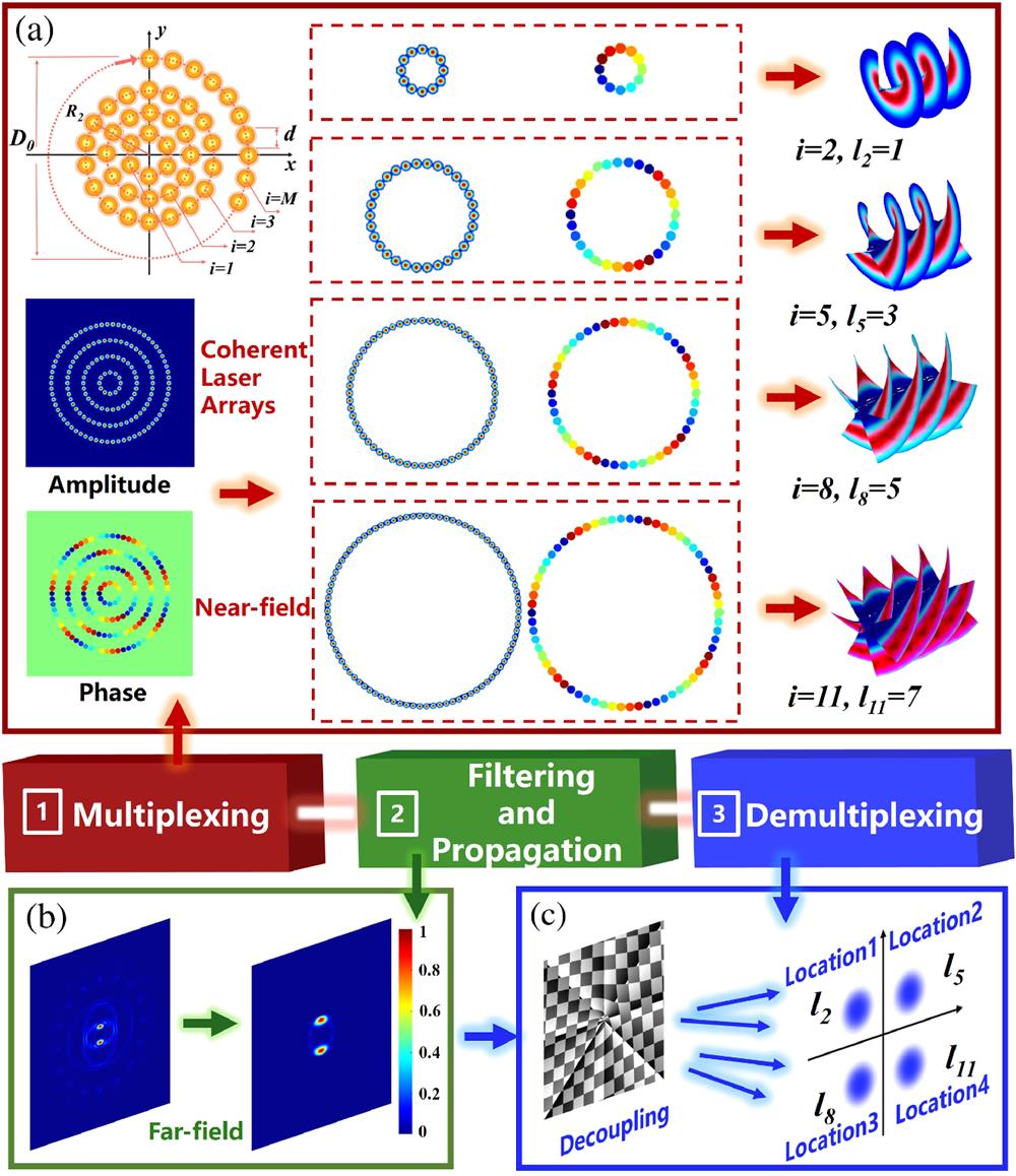
Figure 1 illustrates the principles of structured optical communication by a CBA. As shown in Fig. 1, the system is divided into three parts, including OAM mode multiplexing (Mux), filtering and propagation, and OAM mode demultiplexing (Demux). The main role of Mux is to encode data into OAM superposition modes by a series of sub-arrays, and the number of sub-arrays decides the number of communication channels. Then, the part of filtering and propagation is the responsibility of transmitting assigned information in the form of vortex vortices, which is accompanied by spatial filtering. Finally, the important role of Demux takes the job of receiving and analyzing signals with the method of complex forking gratings; the decoupling results are located in specific locations for convenience.
![]()
Figure 1.Principles of structured optical communication by CBA. (a) The first part: distributed tiled apertures in the near field for generation of multiplexed optical vortices. (b) The second part: filtering and propagation process of the multiplexed OAM modes. (c) The last part: demultiplexing of OAM modes by the designed diffraction grating.
Consider a circularly arranged CBA constructed by -layer sub-arrays, and a bit of data encoded into each sub-array by the designed specific topological charge. The total incident light field is formed by sub-apertures, and then split into layers. The incident light field of the CBA can be described as
As shown in Fig. 1(a), we choose four sub-arrays (, 5, 8, and 11) consisting of 12, 30, 48, and 66 sub-apertures to form a CBA in the near field. The topological charges are set to be 1, 3, 5, and 7 from the internal layer to the external layer, respectively. As the single circular-shaped sub-array has been proven to generate vortex beams successfully,29,30 more sub-arrays could contribute to more multiplexed OAM modes.
Before arriving at the receiving terminal, the formed far-field pattern would go through a period of free-space propagation. During the process, a spatial filtering system should be set in consideration of extra sidelobes, as seen in Fig. 1(b). Then, the results can be represented to be
In the last part, these multiplexed OAM modes will be decoupled by diffraction gratings, and the corresponding expression of demultiplexing results can be written as
The detected light intensity pattern in the far field is expressed as
2.2 Experimental Setup
The designed equivalent experimental device effectively validates the feasibility of optical communication, as demonstrated in Fig. 2, thereby achieving the function of data transmission through a CBC system. First, the laser emitting from the seed is directed through a collimator (CO), followed by a beam expander (BE), a half-wave plate (HWP), and polarizers (P). Subsequently, it reaches the section dedicated to OAM mode multiplexing. The combination of an amplitude-spatial light modulator (A-SLM) and a phase-spatial light modulator (P-SLM1) enables the implementation of this part, thereby achieving a CBC system that is practically equivalent. Next, spatial filtering is achieved through a () device in the green frame during free-space propagation. Lastly, the diffraction grating will be loaded on P-SLM2, and it corresponds to the third part of OAM mode demultiplexing within the blue frame. With the above architecture, three main parts, including OAM mode multiplexing, spatial filtering and propagation, and OAM mode demultiplexing are perfectly integrated into the system.
![]()
Figure 2.Graphical diagram of CBA for the FSOC system. The detailed components of the experimental setup are CO, collimator; BE, beam expander; HWP, half-wave plate; P1–P2, polarizers; L1–L3, lenses; CCD, charge-coupled device; A-SLM, amplitude type spatial light modulator; P-SLM1 and P-SLM2, phase-type spatial light modulators.
3 Results and Discussion
3.1 OAM mode multiplexing Procedure by CBA
To validate the concept of OAM mode multiplexing, we amalgamate the second, fifth, eighth, and eleventh sub-arrays together while assigning them corresponding topological charges of 1, 3, 5, and 7, respectively. If we choose one, two, three, or four of the total sub-arrays at a time, there are a total of 15 possibilities of multiplexed OAM modes, as shown in Figs. 3(a1)–3(a15). Here, we label the layer of sub-array utilized in the patterns. For example, Figure 3(a1) illustrates that only a single OAM mode is multiplexed by one sub-array (), indicating the participation of a sole OAM mode. Figure 3(a6) illustrates two sub-arrays ( and ) that are employed to multiplex OAM modes, resulting in the formation of superposition states. At the condition of superposed two OAM modes, it could be observed that the number of petals in multiplexed OAM modes from the far-field intensity pattern is . As three or more OAM modes are combined, these patterns exhibit two prominent intensity focus points that differ in size.
![]()
Figure 3.Verification results of OAM mode multiplexing by CBA. (a1)–(a15) Simulated results of OAM mode multiplexing in the far field. (b1)–(b15) Experimental results of OAM mode multiplexing in the far field.
When the intensity and phase distribution are loaded on the A-SLM and P-SLM1, respectively, the experimental results exhibit a high degree of consistency with the corresponding theoretical patterns, as shown in Figs. 3(b1)–3(b15). Thus, OAM modes multiplexing have been successfully realized with the help of this strategy. Building upon the findings above, it shows that the expansion of OAM mode multiplexing on a larger scale could be achieved by incorporating additional sub-arrays. In this paper, four sub-arrays fundamentally and essentially fulfill the demands in the process of data transmission.
To further elucidate the underlying mechanism of OAM mode multiplexing by the CBA, this section delves into more variables. As shown in Figs. 4(a1)–4(a3), the emission source is mainly organized by two sub-arrays with opposite topological charges (; ). Except for intrinsic phase differences, extra phase differences of are added between these two sub-arrays, respectively. As depicted in Figs. 4(b1)–4(b3), the corresponding far-field patterns are differed only in rotation directions, which indicates that the initial phase distribution between different layers will not cause essential influences under different conditions. The experimental results further prove it in Figs. 4(c1)–4(c3).
![]()
Figure 4.Intensity and phase distributions of OAM mode multiplexing by two sub-arrays with phase differences or with different sub-apertures. (a1)–(a3) Near-field phase distribution of two sub-arrays with phase differences. (b1)–(b3) Simulated results of multiplexed OAM modes by two sub-arrays with phase differences. (c1)–(c3) Corresponding experimental results. (d1)–(d3) Near-field phase distribution of two sub-arrays with different sub-apertures. (e1)–(e3) Simulated results of multiplexed OAM modes by two sub-arrays with different sub-apertures. (f1)–(f3) Corresponding experimental results.
It is known that a high-capacity FSOC system needs the participation of a large number of OAM modes, which implies the need for the generation of high-order OAM modes. As is well known, the maximum achievable topological charge can be set to be .31 To achieve high-order OAM modes, an increased number of sub-apertures within each sub-array could be utilized. The phase distribution in Figs. 4(d1)–4(d3) exhibits distinct arrangements, with the CBA consisting of 12 () and 18 () sub-apertures, 30 () and 36 () sub-apertures, as well as 48 () and 54 () sub-apertures. Accordingly, the topological charge is set to be and 3 from the internal layer to the external layer, respectively. On one hand, it can be found that the number of sub-apertures does not affect intensity distribution, as shown in Figs. 4(e1)–4(e3). On the other hand, a greater number of sub-apertures in a single sub-array simultaneously enables satisfaction of high-order OAM modes. This observation is further proved by experimental results, as shown in Figs. 4(f1)–4(f3).
3.2 Filtering and Propagation Procedure
The presence of sidelobes in the far field resulting from CBC technology is a commonly observed phenomenon. According to Hou et al.’s investigations, the mode information of OAM beams mainly existing in the central spots, and surrounding sidelobes are formed by the interferences of high-order OAM modes in the CBC system.24 To achieve precise results of the Demux technique, it is essential to incorporate spatial filtering into the free-space propagation procedure. Spatial filtering plays a crucial role in improving the accuracy and reliability of the Demux technique by effectively removing unwanted interference or noise from the intensity signals. This process involves applying mathematical algorithms that exploit the spatial characteristics of the signals to separate them effectively. Then, the filtered signals can be analyzed or utilized for various applications, such as communication systems, imaging technologies, or scientific research. The far-field patterns are illustrated in Figs. 5(a1)–5(a15). Compared with Figs. 5(b1)–5(b15), it is demonstrated that the experimental results exhibit a high level of concordance with the theoretical results. The spatial technology effectively eliminates the sidelobes, ensuring a prominent main lobe. In practice, the limited ability of spatial filtering could lead to some residual sidelobes in the experimental results. However, the proposed decoupling method exhibits robustness to tolerate this phenomenon.
![]()
Figure 5.Intensity distribution in the far field by spatial filtering between multiplexing and demultiplexing procedures. (a1)–(a15) Simulated results. (b1)–(b15) Corresponding experimental results.
3.3 OAM Mode Demultiplexing Procedure by Complex Forking Gratings
Diffraction grating as a decoupling strategy is commonly to be utilized for analysis of OAM mode information. In this work, the complex forking grating is chosen as the diffraction grating in the integrated CBC system and possesses a binary function. The first aspect involves the demultiplexing of four specific OAM modes, each possessing topological charges of 1, 3, 5, and 7. The second aspect pertains to the spatial separation of these four OAM modes into designed locations at , 45 deg, , and 135 deg angles, denoted as locations 1 to 4, as shown in Fig. 1(c). This is because each forking grating is the superposition of the spiral phase and blazed grating phase. Surely, the coordination in each location can be changed by a blazed gratings phase according to its parameters, and the demultiplexed OAM modes are decided by a spiral phase according to topological charges of the participating OAM modes.
The appearance of a Gaussian spot at a location after passing through the complex forking gratings indicates the presence of the corresponding OAM mode component. For example, if the OAM mode () goes through free-space propagation, the Gaussian point will appear at Location 1, as shown in Fig. 6(a9). If both OAM modes ( and ) go through free-space propagation, the Gaussian point will appear at Location 1 and Location 3 simultaneously, as depicted in Fig. 6(a10). Theoretically, by employing the efficient decoupling methods, it could precisely judge the existing OAM modes in patterns, depicted by white circles in Figs. 6(a1)–6(a15). The experimental results are shown in Figs. 6(b1)–6(b15), and the detected results could be recognized. If no sub-array is added, there are 16 results of OAM mode multiplexing in total. These 16 far-field patterns formed by specific groups of sub-arrays could be utilized to encode, which means it can transmit multiple pieces of information by loading on the far-field light field.
![]()
Figure 6.Verification results of OAM mode demultiplexing by complex forking gratings. (a1)–(a15) Simulated results of OAM mode multiplexing in the far field. (b1)–(b15) Experimental results of OAM mode multiplexing in the far field.
The field intensities overlap between the simulated and experimental results could be represented by correlation, which is defined to be , where , and the correlation value is within the range of 0–1. In the above expression, represents the corresponding mean value of theoretical far-field intensity or . On the basis of calculated results, the correlation values between the simulated and experimental results in Figs. 3 and 5 are within the range of 0.85 to 0.95, which means the simulated results of far-field light distribution match well with the corresponding experimental results, regardless of spatial filtering. However, the correlation value in Fig. 6 decreases to around 0.5. The reason for this phenomenon is the unstable factors in the experimental equipment. It is most probable that the offset of light spots in the path result in the failure of the alignment between the experimental and calculated decoupling results. Note that the whole decoupling process is only influenced by the intensity in the central Gaussian points, so the correlation values have no relationship with the recognition accuracy.
Note that the phase coincidence is hard to meet in a practical CBC system. Herein, we further consider how the existence of phase errors affects the demultiplexing process. As shown in Fig. 7, we select several specific codes including 0001, 1010, 1110, and 1111 for comparison as the added phase errors () to be 0, 0.3, 0.6, 1.0, and 1.5, respectively. These four codes are varied by different numbers of multiplexed OAM modes that are required to be recognized. Obviously, if phase errors are introduced in the whole system, it will affect the precision of demultiplexing results to some extent. When the introduced phase errors are below 1.0, most of the codes can be precisely identified. Once exceeding the value, the error rate will significantly increase, even disabled up to 1.5. For example, the error codes 1010 in Figs. 7(b4)–7(b5), 1110 in Figs. 7(c4)–7(c5), and 1111 in Fig. 7(d5) are not recognized correctly. In consideration of simplifying the system and ensuring the quality of communication links, we only perform data transmission in ideal scenarios.
![]()
Figure 7.Comparison between the simulated intensity proportion of ideal OAM modes and practical OAM modes before and after the demultiplexing process. Results of the codes to be (a1)–(a5) 0001; (b1)–(b5) 1010; (c1) – (c5) 1110, and (d1)–(d5) 1111 as introduced phase errors to be 0, 0.3, 0.6, 1.0, and 1.5, respectively.
3.4 Data Transmission by an Integrated CBC System
By the proposed integrated CBC system, we successfully present transmission of the image called “Ke Xiaobo” at a resolution of . Due to a single pixel consisting of 8 bits, the number of transmitting code elements is , equaling 10,000 in total. The detailed recognition process of a single pixel is on the basis of image processing. For example, if a single pixel equaling 74 is chosen, it should be transferred to binary coding 01001010 first. These eight code elements are divided into two parts. The first four bits 0100 could be loaded by the intensity and phase in Figs. 8(b1)–8(c1), and the last four bits 1010 could be loaded on the intensity and phase in Figs. 8(b2)–8(c2). The multiplexing results are given in Figs. 8(d1)–8(d2). After a period of filtering and free-space propagation, the obtained patterns are shown in Figs. 8(e1)–8(e2). To realize the automatic detection process, these two OAM demultiplexing results in Figs. 8(f1)–8(f2) will be transferred into a gray-scale image in Figs. 8(g1)–8(g2) for image processing. Next, we can define the existence or inexistence of the mode to be 1 or 0. Four-bit binary coding can be realized by the above four OAM modes, which means data transmission can be further conducted. The corresponding encoding results 0100 and 1010 will be formed according to marked Gaussian light spots in Figs. 8(h1) and 8(h2). Finally, the single pixel 74 is successfully coded. Based on the above findings, these different OAM multiplexing results can support encoding information from 0 to 15. If all pixels () in the image of Ke Xiaobo need to be expressed, the amount of far-field patterns is .
![]()
Figure 8.Detailed process of data transmission by integrated CBC system. (a) Original input image. (b1)–(b2) Intensity and (c1)–(c2) phase distributions. (d1)–(d2) Far-field patterns and (e1)–(e2) patterns after spatial filtering. (f1)–(f2) OAM mode demultiplexing results. (g1)–(g2) Transferred gray-scale patterns. (h1)–(h2) The encoding results for 0100 and 1010 code elements, respectively. (i) Recovered output image. (j) Error rate at different locations. (k1)–(k4) The separate four Gaussian spots inconsistent with Fig. 8(f2). (k5) Error rate at different thresholds.
The error rate at different locations is shown in Fig. 8(j), and the bar chart displays the error rate of the four locations. It is demonstrated that the BER for the transmission of the image is 0.47%, which corresponds to the ratio of incorrectly coded elements to all coding elements. It is obvious that the result falls within the range of , meeting the requirements of a structured optical communication system. Note that if the number of transmitting bits is large enough, then BER will decrease to some extent, which means it could satisfy more requirements. Owing to the efficient and careful spatial filtering, the whole detection process is in high precision of 98.58%. The presence of background noise and measurement instability leads to the identification of error code elements, as depicted in Fig. 8.
During the transferring process of the gray-scale image, the setting of thresholds is the most crucial stage to confirm the existence of these four OAM modes. As can be seen in Figs. 8(k1)–8(k4), the four Gaussian spots in correspondence with each code have been separated into four regions, and the fixed area, marked by red circles, will be used for the settings of the threshold. If the intensity value in such a small region is higher than the thresholds, the corresponding OAM mode will be detected; otherwise, it will set to be zero. The method is similar to the gray-scale algorithms proposed by Fu et al.32 As can be seen in Fig. 8(k5), the optimal performance of a structured optical communication system can be achieved by employing a perfect combination of the threshold in these four locations. We set the combination with the lowest error rate to be standard, and the error rates become larger as the threshold difference increases. Thus. we finally verified the lowest BER to be 0.47% after careful comparison between these different circumstances.
4 Conclusion
To sum up, this work proposes an integrated CBC system for free-space structured optical communication. The system is divided into three parts, including OAM mode multiplexing, filtering and propagation, and OAM mode demultiplexing. Such a designed system preliminarily verifies the possibilities of binary encoding data transmission by CBC technology, and it achieved impressive performance; for example, the BER is as low as 0.47%, and the recognition precision is as high as 98.58%. Divergent-free or non-diffraction beams will be further developed to improve the transmission distances of optical links as supported by flexible beam shaping by coherent beam arrays. In addition, if a larger-scale CBC system was applied to optical links, more channels could be set to improve the efficiency of the FSOC. An FSOC with ultra-long communication distance and high-performance communication quality by such an integrated CBC system possesses great prospects for the future.
Yuqiu Zhang is currently a postdoc at the National University of Defense Technology. She received her PhD in optical engineering from the National University of Defense Technology in 2022. Her current research interests cover laser beam atmospheric propagation and light field regulation. She is the author of more than 20 journal papers.
Pu Zhou is a professor at the National University of Defense Technology. He received his PhD in optical engineering from the National University of Defense Technology in 2009. He is the author of more than 100 journal papers. His current research interests include fiber laser technology and interdisciplinary fields.
Biographies of the other authors are not available.
References
[2] A. Forbes, M. de Oliveira, M. R. Dennis. Structured light. Nat. Photonics, 15, 253-262(2021).
[3] A. E. Willner. OAM light for communications. Opt. Photonics News, 32, 34-41(2021).
[10] Y. Awaji, N. Wada, Y. Toda. Demonstration of spatial mode division multiplexing using Laguerre-Gaussian mode beam in telecom-wavelength, 551-552(2010).
[16] H. Hao et al. 100 Tbit/s free-space data link using orbital angular momentum mode division multiplexing combined with wavelength division multiplexing, 1-3(2013).
[17] J. Wang et al. In N-dimentional multiplexing link with 1.036-Pbit/s transmission capacity and 112.6-bit/s/Hz spectral efficiency using OFDM-8QAM signals over 368 WDM pol-muxed 26 OAM modes, 1-3(2014).

Set citation alerts for the article
Please enter your email address
© Copyright 2018-2021 | Chinese Laser Press. All Rights Reserved 沪ICP备15018463号-20