
Yuhao Pan, Li Li, Xiaolong Zhou, Dongyu Huang, Zemin Shen, Jian Wang, Chuanfeng Li, Guangcan Guo, "Fabrication, testing, and assembly of high-finesse optical fiber microcavity for molecule cavity QED experiment," Chin. Opt. Lett. 20, 122702 (2022)
- Chinese Optics Letters
- Vol. 20, Issue 12, 122702 (2022)
Abstract
1. Introduction
In ultracold molecules, complex rovibrational energy levels enrich the spectrum from microwave to visible light, and the large permanent dipole moment empowers strong intermolecular interaction[1,2], making the ultracold molecule a new form of quantum matter for quantum chemistry[3–5], quantum simulation[6,7], quantum computation[8,9], and quantum precision measurement[10–12]. To prepare molecules for the ultracold regime, two ways of producing ultracold molecules have been developed: direct cooling with special molecule species like SrF and CaF[13–17] and association from the pre-cooled atoms. In association with pre-cooled atoms, the constituent atoms are usually chosen to be easily cooled to the quantum degeneracy regime and are associated by photoassociation[18], Feshbach resonance combined with stimulated Raman adiabatic passage (STRAP)[19–21], spin-motional coupling[22], and optical Raman transition in optical tweezers[23]. Cavity quantum electrodynamics (QED) concentrates on the study of the interaction between light and matter, which plays a significant role in single-photon generation[24,25], quantum network[26], and quantum computation[27]. By tailoring the spatial boundary condition, the optical cavity enhances the resonant transition of interacting matter (called the Purcell effect) and even induces the strong coupling between cavity mode and matter forming dressed states if the coupling strength overcomes the dissipation strength. In molecule cavity QED experimental research, the optical cavity enhances the resonant energy transitions and suppresses other off-resonant transitions of complex rovibrational energy levels, which can form a near-closed optical cycle for manipulation and fluorescence detection of polyatomic molecules[28]. It can also greatly increase the production efficiency of photoassociated molecules and narrows the final state distribution to the desired state[29–31]. With the help of the strong coupling of cavity mode and molecules, the optical cavity offers a non-demolition detection of the internal state of molecules without destructively converting associated molecules to the constituent atoms or molecular ions for detection[32]. Besides, the strong coupling effect will modify the photochemical and photophysical processes in molecules, empowering the research of cavity-controlled chemistry[33,34].
The optical fiber Fabry–Pérot microcavity featuring small mode volume and high finesse is a good candidate for ultracold molecules experimental research requiring large system cooperativity[35,36]. Different from single atoms, the coupling strength of the cavity mode and molecules will be additionally reduced by the finite wavefunction overlap between the excited bound state and the ground molecular state described by
2. Experiment and Results
2.1. Fabrication of fiber cavity mirrors
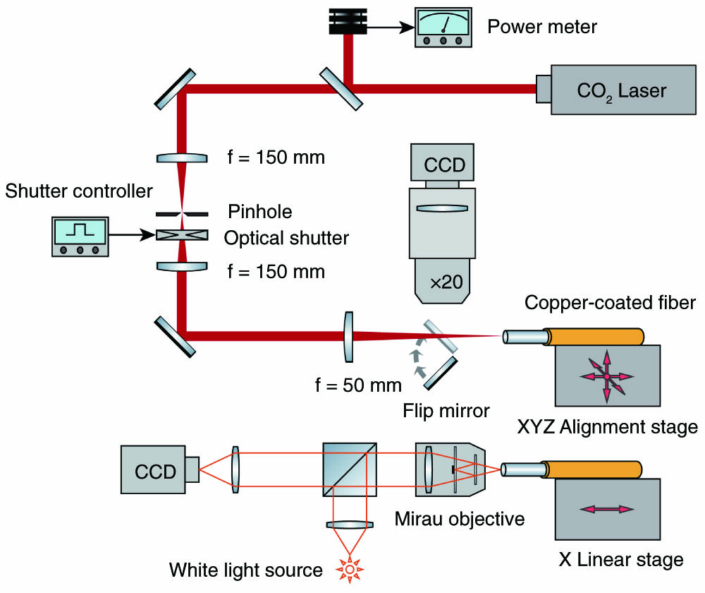
Fabrication of the fiber cavity mirrors plays a central role in producing a high-finesse optical cavity, which directly determines the surface profile of cavity mirrors and optical properties. Among the various fabrication methods[41], laser ablation can polish the surface of the cavity mirror with the roughness of sub-nanometers and can cover a wide radius of curvature (ROC) range of concave mirrors from tens of micrometers to thousands of micrometers. As Fig. 1 shows, our homemade fiber mirrors fabrication system mainly consists of a
Sign up for Chinese Optics Letters TOC. Get the latest issue of Chinese Optics Letters delivered right to you!Sign up now
![]()
Figure 1.Experimental setup of CO2 laser ablation system and surface profiler for the fabrication of fiber cavity mirrors.
2.2. Testing of fiber cavity mirrors
The contour plot describing the fabricated fiber cavity mirror is shown in Fig. 2(a) derived from our surface profiler, which is a near-spherical concave surface. To compare our laser-ablated cavity mirror with the ideal spherical Fabry–Pérot cavity mirror, we fit the central cross section of the fiber cavity mirror with a circle equation in Fig. 2(b). Then, the difference between the data and fitting function is derived in Fig. 2(c). The effective diameter of the fiber cavity mirror is defined as the range where the difference is below a tenth of the 744 nm working wavelength, so our fiber cavity mirror is about 40 µm in diameter. In the high-finesse optical fiber microcavity, the frequency splitting of different polarizations is sensitive to the eccentricity of the elliptical cavity mirrors, which should be minimized for a polarization-degenerate cavity. The differential phase shift between the two polarization eigenmodes from one elliptical cavity mirror is[42,43]
![]()
Figure 2.(a) Contour plot of the concave fiber cavity mirror. The horizontal gray dashed line is the baseline of the mirror orientation (θ = 0°), and the θ stands for the relative angle of different mirror orientations for cross sections around the mirror center. (b) Cross section of the concave fiber cavity mirror fitted by a circular equation. (c) Difference between the measured Z data and the fitting Z data on the scale of the 744 nm working wavelength. (d) The distribution of ROC for mirror orientations fitted by an ellipsoid model, and the θ0 stands for the relative angle of the mirror orientation at the major axis.
Coated with the highly reflective coating at the multiwavelengths of 744 nm, 780 nm, and 850 nm, the optical properties of the fabricated fiber cavity mirrors need to be tested in a form of a Fabry–Pérot cavity with the help of a high-precision alignment testing platform. As Fig. 3 shows, our testing platform has six degrees of freedom to control the relative position and orientation between the two fiber cavity mirrors forming the optical cavity. The fiber cavity mirror in the right can travel in the three-dimensional direction driven by three one-axis linear stages and can oscillate fast along the optical cavity axis in several micrometers actuated by a piezo to scan the cavity length for a transmission signal. The fiber rotator can rotate the relative angle between the major axes of the two elliptical cavity mirrors in the right to suppress the frequency splitting of different polarizations[42,43]. For the fiber cavity mirror in the left, the position is kept still, but the orientation can be rotated in the two orthogonal directions. The two microscopes are placed in the vertical and horizontal directions for the coarse alignment of the two fiber cavity mirrors and cavity length measurement. A probe laser is sent into the right fiber cavity mirror, and the transmission signal is detected at the output of the left fiber cavity mirror and is displayed on the oscilloscope. Optimizing the transmission signal by finely adjusting the position and orientation of the two fiber cavity mirrors can reach the best mode-matching efficiency between the optical fiber mode and cavity mode[44]. As Fig. 4(a) shows, the transmission peak of the optical fiber microcavity at the 744 nm working wavelength is recorded, and the full-width at half-maximum (FWHM) is measured to be about 62 MHz by comparing it with the two 710 MHz electro-optic modulator (EOM)-generated sidebands. With the cavity length of 100 µm measured by the microscope, the finesse at 744 nm is
![]()
Figure 3.Experimental setup of the high-precision alignment testing platform.
![]()
Figure 4.(a) Transmission signal of optical fiber microcavity at the 744 nm working wavelength with the cavity length of 100 µm. (b) Transmission peaks of optical fiber microcavity consisting of two low-transmission (LT) cavity mirrors before annealing (black line) and after annealing (red line).
After basic testing, annealing is applied to the two fiber cavity mirrors to increase the finesse of the optical cavity, which proves to be an effective way of reducing the absorption loss of
| Types | Before Annealing | After Annealing | ||
|---|---|---|---|---|
| HT + LT | 37,120 | 31,175 | 41,328 | 40,543 |
| LT + LT | 60,735 | 69,785 | 112,166 | 111,080 |
Table 1. The Finesse of Two Optical Fiber Microcavities before and after Annealing
2.3. Assembly of optical fiber microcavity
For coupling to the
![]()
Figure 5.(a) Assembly of the optical fiber microcavity consists of fiber cavity mirrors, V grooves, piezos, copper wires, spacers, and the baseplate. (b) Finesse change of the optical fiber microcavity tested in the ultra-high vacuum chamber at the 850 nm locking wavelength for 4 months. The fluctuation of the measured finesse results from the uncertainty of the measurement method.
Some researchers report the finesse degradation of high-finesse optical fiber microcavity in ultra-high vacuum for UV wavelength[47] and near-infrared (NIR) wavelength[48]. So, we test our optical fiber microcavity assembly in an ultra-high vacuum chamber (< 10-9 mbar) for months. By recording the finesse at the 850 nm locking wavelength, the finesse degradation is not observed in our high-finesse optical fiber microcavity, as shown in Fig. 5(b). The finesse of our optical fiber microcavity at 850 nm is kept around 20,000, proving that the optical fiber microcavity assembly is compatible with the ultra-high vacuum environment.
3. Conclusion
In this Letter, we illustrate the fabrication of fiber cavity mirrors by the
References
[1] J. L. Bohn, A. M. Rey, J. Ye. Cold molecules: progress in quantum engineering of chemistry and quantum matter. Science, 357, 1002(2017).
[2] S. A. Moses, J. P. Covey, M. T. Miecnikowski, D. S. Jin, J. Ye. New frontiers for quantum gases of polar molecules. Nat. Phys., 13, 13(2017).
[3] Y. Liu, M.-G. Hu, M. A. Nichols, D. Yang, D. Xie, H. Guo, K.-K. Ni. Precision test of statistical dynamics with state-to-state ultracold chemistry. Nature, 593, 379(2021).
[4] W. G. Tobias, K. Matsuda, J.-R. Li, C. Miller, A. N. Carroll, T. Bilitewski, A. M. Rey, J. Ye. Reactions between layer-resolved molecules mediated by dipolar spin exchange. Science, 375, 1299(2022).
[5] H. Yang, X.-Y. Wang, Z. Su, J. Cao, D.-C. Zhang, J. Rui, B. Zhao, C.-L. Bai, J.-W. Pan. Evidence for the association of triatomic molecules in ultracold 23Na40K + 40K mixtures. Nature, 602, 229(2022).
[6] H. Weimer. Quantum simulation of many-body spin interactions with ultracold polar molecules. Mol. Phys., 111, 1753(2013).
[7] T. Schuster, F. Flicker, M. Li, S. Kotochigova, J. E. Moore, J. Ye, N. Y. Yao. Floquet engineering ultracold polar molecules to simulate topological insulators. Phys. Rev. A, 103, 063322(2021).
[8] P. Yu, L. W. Cheuk, I. Kozyryev, J. M. Doyle. A scalable quantum computing platform using symmetric-top molecules. New J. Phys., 21, 093049(2019).
[9] S. F. Yelin, K. Kirby, R. Côté. Schemes for robust quantum computation with polar molecules. Phys. Rev. A, 74, 050301(2006).
[10] V. Andreev, D. G. Ang, D. DeMille, J. M. Doyle, G. Gabrielse, J. Haefner, N. R. Hutzler, Z. Lasner, C. Meisenhelder, B. R. O’Leary, C. D. Panda, A. D. West, E. P. West, X. Wu, A. Collaboration. Improved limit on the electric dipole moment of the electron. Nature, 562, 355(2018).
[11] T. Bilitewski, L. De Marco, J.-R. Li, K. Matsuda, W. G. Tobias, G. Valtolina, J. Ye, A. M. Rey. Dynamical generation of spin squeezing in ultracold dipolar molecules. Phys. Rev. Lett., 126, 113401(2021).
[12] B. L. Augenbraun, Z. D. Lasner, A. Frenett, H. Sawaoka, C. Miller, T. C. Steimle, J. M. Doyle. Laser-cooled polyatomic molecules for improved electron electric dipole moment searches. New J. Phys., 22, 022003(2020).
[13] E. B. Norrgard, D. J. McCarron, M. H. Steinecker, M. R. Tarbutt, D. DeMille. Submillikelvin dipolar molecules in a radio-frequency magneto-optical trap. Phys. Rev. Lett., 116, 063004(2016).
[14] S. Ding, Y. Wu, I. A. Finneran, J. J. Burau, J. Ye. Sub-Doppler cooling and compressed trapping of YO molecules at µK temperatures. Phys. Rev. X, 10, 021049(2020).
[15] L. Anderegg, B. L. Augenbraun, E. Chae, B. Hemmerling, N. R. Hutzler, A. Ravi, A. Collopy, J. Ye, W. Ketterle, J. M. Doyle. Radio frequency magneto-optical trapping of CaF with high density. Phys. Rev. Lett., 119, 103201(2017).
[16] L. Anderegg, L. W. Cheuk, Y. Bao, S. Burchesky, W. Ketterle, K.-K. Ni, J. M. Doyle. An optical tweezer array of ultracold molecules. Science, 365, 1156(2019).
[17] Y. Wu, J. J. Burau, K. Mehling, J. Ye, S. Ding. High phase-space density of laser-cooled molecules in an optical lattice. Phys. Rev. Lett., 127, 263201(2021).
[18] K. M. Jones, E. Tiesinga, P. D. Lett, P. S. Julienne. Ultracold photoassociation spectroscopy: long-range molecules and atomic scattering. Rev. Mod. Phys., 78, 483(2006).
[19] C. Chin, R. Grimm, P. Julienne, E. Tiesinga. Feshbach resonances in ultracold gases. Rev. Mod. Phys., 82, 1225(2010).
[20] K. Bergmann, H.-C. Nägerl, C. Panda, G. Gabrielse, E. Miloglyadov, M. Quack, G. Seyfang, G. Wichmann, S. Ospelkaus, A. Kuhn, S. Longhi, A. Szameit, P. Pirro, B. Hillebrands, X.-F. Zhu, J. Zhu, M. Drewsen, W. K. Hensinger, S. Weidt, T. Halfmann, H.-L. Wang, G. S. Paraoanu, N. V. Vitanov, J. Mompart, T. Busch, T. J. Barnum, D. D. Grimes, R. W. Field, M. G. Raizen, E. Narevicius, M. Auzinsh, D. Budker, A. Pálffy, C. H. Keitel. Roadmap on STIRAP applications. J. Phys. B, 52, 202001(2019).
[21] L. D. Marco, G. Valtolina, K. Matsuda, W. G. Tobias, J. P. Covey, J. Ye. A degenerate Fermi gas of polar molecules. Science, 363, 853(2019).
[22] X. He, K. Wang, J. Zhuang, P. Xu, X. Gao, R. Guo, C. Sheng, M. Liu, J. Wang, J. Li, G. V. Shlyapnikov, M. Zhan. Coherently forming a single molecule in an optical trap. Science, 370, 331(2020).
[23] Y. Yu, K. Wang, J. D. Hood, L. R. B. Picard, J. T. Zhang, W. B. Cairncross, J. M. Hutson, R. Gonzalez-Ferez, T. Rosenband, K.-K. Ni. Coherent optical creation of a single molecule. Phys. Rev. X, 11, 031061(2021).
[24] N. Tomm, A. Javadi, N. O. Antoniadis, D. Najer, M. C. Löbl, A. R. Korsch, R. Schott, S. R. Valentin, A. D. Wieck, A. Ludwig, R. J. Warburton. A bright and fast source of coherent single photons. Nat. Nanotechnol., 16, 399(2021).
[25] Y. Huang, Z. Dang, X. He, Z. Fang. Engineering of single-photon emitters in hexagonal boron nitride [Invited]. Chin. Opt. Lett., 20, 032701(2022).
[26] M. Brekenfeld, D. Niemietz, J. D. Christesen, G. Rempe. A quantum network node with crossed optical fibre cavities. Nat. Phys., 16, 647(2020).
[27] S. Daiss, S. Langenfeld, S. Welte, E. Distante, P. Thomas, L. Hartung, O. Morin, G. Rempe. A quantum-logic gate between distant quantum-network modules. Science, 371, 614(2021).
[28] D. Wang, H. Kelkar, D. Martin-Cano, D. Rattenbacher, A. Shkarin, T. Utikal, S. Götzinger, V. Sandoghdar. Turning a molecule into a coherent two-level quantum system. Nat. Phys., 15, 483(2019).
[29] T. Kampschulte, J. Hecker Denschlag. Cavity-controlled formation of ultracold molecules. New J. Phys., 20, 123015(2018).
[30] J. Pérez-Ríos, M. E. Kim, C.-L. Hung. Ultracold molecule assembly with photonic crystals. New J. Phys., 19, 123035(2017).
[31] D. Wellnitz, S. Schütz, S. Whitlock, J. Schachenmayer, G. Pupillo. Collective dissipative molecule formation in a cavity. Phys. Rev. Lett., 125, 193201(2020).
[32] M. Zhu, Y.-C. Wei, C.-L. Hung. Resonator-assisted single-molecule quantum state detection. Phys. Rev. A, 102, 023716(2020).
[33] F. Herrera, F. C. Spano. Cavity-controlled chemistry in molecular ensembles. Phys. Rev. Lett., 116, 238301(2016).
[34] F. J. Garcia-Vidal, C. Ciuti, T. W. Ebbesen. Manipulating matter by strong coupling to vacuum fields. Science, 373, eabd0336(2021).
[35] D. Hunger, T. Steinmetz, Y. Colombe, C. Deutsch, T. W. Hänsch, J. Reichel. A fiber Fabry-Perot cavity with high finesse. New J. Phys., 12, 065038(2010).
[36] H. Pfeifer, L. Ratschbacher, J. Gallego, C. Saavedra, A. Faßbender, A. von Haaren, W. Alt, S. Hofferberth, M. Köhl, S. Linden, D. Meschede. Achievements and perspectives of optical fiber Fabry-Perot cavities. Appl. Phys. B, 128, 29(2022).
[37] L. Zhou, C. Wang, A. Yi, C. Shen, Y. Zhu, K. Huang, M. Zhou, J. Zhang, X. Ou. Photonic crystal nanobeam cavities based on 4H-silicon carbide on insulator. Chin. Opt. Lett., 20, 031302(2022).
[38] L. Fang, X. Gan, J. Zhao. High-Q factor photonic crystal cavities with cut air holes [Invited]. Chin. Opt. Lett., 18, 111402(2020).
[39] S. Subramanian, S. Vincent, F. Vollmer. Effective linewidth shifts in single-molecule detection using optical whispering gallery modes. Appl. Phys. Lett., 117, 151106(2020).
[40] M. A. Bellos, D. Rahmlow, R. Carollo, J. Banerjee, O. Dulieu, A. Gerdes, E. E. Eyler, P. L. Gould, W. C. Stwalley. Formation of ultracold Rb2 molecules in the v″ = 0 level of the a3Σu+ state via blue-detuned photoassociation to the 13πg state. Phys. Chem. Chem. Phys., 13, 18880(2011).
[41] M. H. Bitarafan, R. G. DeCorby. On-chip high-finesse Fabry-Perot microcavities for optical sensing and quantum information. Sensors, 17, 1748(2017).
[42] M. Uphoff, M. Brekenfeld, G. Rempe, S. Ritter. Frequency splitting of polarization eigenmodes in microscopic Fabry-Perot cavities. New J. Phys., 17, 013053(2015).
[43] J.-M. Cui, K. Zhou, M.-S. Zhao, M.-Z. Ai, C.-K. Hu, Q. Li, B.-H. Liu, J.-L. Peng, Y.-F. Huang, C.-F. Li, G.-C. Guo. Polarization nondegenerate fiber Fabry-Perot cavities with large tunable splittings. Appl. Phys. Lett., 112, 171105(2018).
[44] J. Gallego, S. Ghosh, S. K. Alavi, W. Alt, M. Martinez-Dorantes, D. Meschede, L. Ratschbacher. High-finesse fiber Fabry-Perot cavities: stabilization and mode matching analysis. Appl. Phys. B, 122, 47(2016).
[45] Y. Zhao, Y. Wang, H. Gong, J. Shao, Z. Fan. Annealing effects on structure and laser-induced damage threshold of Ta2O5/SiO2 dielectric mirrors. Appl. Surf. Sci., 210, 353(2003).
[46] B. Brandstätter, A. McClung, K. Schüppert, B. Casabone, K. Friebe, A. Stute, P. O. Schmidt, C. Deutsch, J. Reichel, R. Blatt, T. E. Northup. Integrated fiber-mirror ion trap for strong ion-cavity coupling. Rev. Sci. Instrum., 84, 123104(2013).
[47] D. Gangloff, M. Shi, T. Wu, A. Bylinskii, B. Braverman, M. Gutierrez, R. Nichols, J. Li, K. Aichholz, M. Cetina, L. Karpa, B. Jelenković, I. Chuang, V. Vuletić. Preventing and reversing vacuum-induced optical losses in high-finesse tantalum (V) oxide mirror coatings. Opt. Express, 23, 18014(2015).
[48] J. Gallego, W. Alt, T. Macha, M. Martinez-Dorantes, D. Pandey, D. Meschede. Strong purcell effect on a neutral atom trapped in an open fiber cavity. Phys. Rev. Lett., 121, 173603(2018).


Set citation alerts for the article
Please enter your email address

© Copyright 2018-2021 | Chinese Laser Press. All Rights Reserved 沪ICP备15018463号-20