1Shanghai Jiao Tong University, School of Physics and Astronomy, State Key Laboratory of Advanced Optical Communication Systems and Networks, Shanghai, China
2Shanghai Research Center for Quantum Sciences, Shanghai, China
3Shandong Normal University, Collaborative Innovation Center of Light Manipulation and Applications, Jinan, China
Guangzhen Li, Luojia Wang, Rui Ye, Shijie Liu, Yuanlin Zheng, Luqi Yuan, Xianfeng Chen, "Observation of flat-band and band transition in the synthetic space," Adv. Photon. 4, 036002 (2022)
Copy Citation Text
Constructions of synthetic lattices in modulated ring resonators attract growing attention to interesting physics beyond the geometric dimensionality, where complicated connectivities between resonant frequency modes are explored in many theoretical proposals. We implement experimental demonstration of generating a stub lattice along the frequency axis of light, in two coupled ring resonators of different lengths, with the longer one dynamically modulated. Such a synthetic photonic structure intrinsically exhibits the physics of flat band. We show that the time-resolved band structure read-out from the drop-port output of the excited ring is the intensity projection of the band structure onto a specific resonant mode in the synthetic momentum space, where gapped flat band, mode localization effect, and flat-to-nonflat band transition are observed in experiments and verified by simulations. This work provides evidence for constructing a synthetic stub lattice using two different rings, which, hence, makes a solid step toward experimentally constructing complicated lattices in multiple rings associated with synthetic frequency dimensions.
Synthetic dimensions in photonics have attracted broad interest in recent years.1–4 They promise new ways to study fundamental physical phenomena with exotic artificial connectivities5–9 and manipulate light in various ways,10–18 pointing toward exploration of higher-dimensional physics, beyond three dimensions.19–21 Among recent experimental achievements, different degrees of freedom of light, including arrival times of pulses,10,11 frequencies,22–24 and modal dimensions,8 have been used to construct synthetic dimensions. Hence, a variety of novel physics have been demonstrated in synthetic dimensions, such as the photonic topological insulator,8 the Hall ladder with effective magnetic flux,25 the trajectory of dynamic band structures,26 and the topological funneling with non-Hermitian physics,27 physical models of which are hard to build in structures with only spatial dimensions.
Among these platforms, the dynamically modulated ring resonator system has manifested as a powerful platform where resonant modes with equally spaced frequencies are coupled by external modulation, and then the synthetic frequency dimension is created.22,23 The modulation applied by external voltages provides the unique advantages of breaking the constraint of fixed geometric structures after fabrication and thus provides an important possibility of achieving complicated functionalities with great experimental flexibility and reconfigurability.4 Experimental implementations have been performed in ring resonator systems including fiber loops or on-chip microrings,24–26,28–31 and physical phenomena including band structures measurements,24,26 spectral Bloch oscillations,29 and non-Hermitian topology30,32 have been shown, where one ring or two identical rings have been used. On the other hand, theoretical proposals have been explored where formations of photonic lattice with different lengths of rings can enable intriguing studies of rich physics, such as the Haldane model,7 topological quench dynamics,33 two-dimensional Lieb lattice,34 three-dimensional topological insulator,35 and high-order topologies.36,37 However, to realize these theoretical proposals requires constructing complicated lattice structures beyond simple lines or square geometries in synthetic space in two or more rings of different lengths. Therefore, as a crucial step further, one desires to first prove the capability of creating a complex lattice in two coupled rings of different lengths in the experiment.
In this work, we experimentally couple two rings of different lengths, where one ring undergoes the dynamic modulation, and construct a photonic stub lattice (also called one-dimensional Lieb lattice)38–42 associated with synthetic frequency dimension. Such a configuration is not straightforward to construct, compared with lattices in one ring24,26 or in two identical rings.32 One intrinsic feature of the stub lattice is the natural existence of the flat (dispersionless) band.43–49 In our experiments, the time-resolved energy bands from the drop-port output of the excited ring are obtained, corresponding to the projection of the band structures of the stub lattice, which, however, is on the synthetic dimension. Moreover, by exciting the resonant modes through the selected input port of one ring and recording the output transmission from the same ring, we observe the effective localization of the resonant modes near the flat band. Such a flat band in synthetic space can further be modified by adding the long-range couplings in the modulation, which leads to the transition from the flat to nonflat bands. By combining theoretical analysis, we show that coupling two rings at different lengths leads to experimental observations where bands are projected onto superposition modes, which is very different from previous works on flat-band physics. Such a feature is unique in the platform of synthetic dimensions with modulated ring resonators, so our work, therefore, exhibits a crucial step toward constructing more complicated synthetic lattices in multiple rings of different lengths.
Sign up for Advanced Photonics TOC. Get the latest issue of Advanced Photonics delivered right to you!Sign up now
2 Materials and Methods
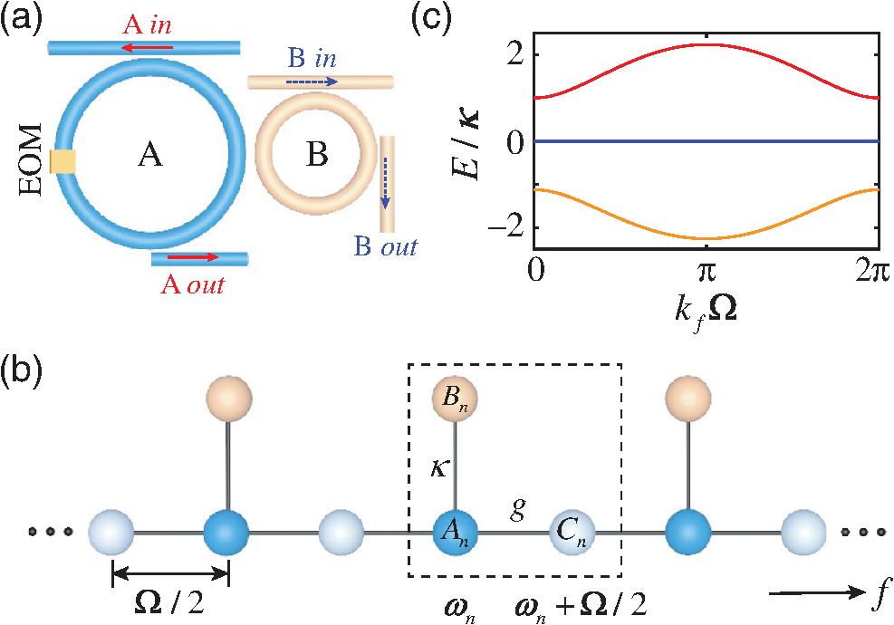
We start by illustrating the model of two modulated rings of different lengths, labeled as A and B in Fig. 1(a). In the absence of group velocity dispersion, the ring resonator supports a set of modes with equally spaced frequencies. If we set the central resonant frequency at , the ’th mode in the ring has the frequency , where is the free spectral range (FSR) of ring , and is the group velocity. We consider the length of ring () twice as long as the length of ring (), i.e., , which gives . The electro-optic modulator (EOM) is placed inside ring with the modulation frequency , the modulation strength , and the modulation phase , which provides the connectivity between adjacent resonant modes in ring , while there is no modulator in ring , so resonant modes in ring remain unconnected. Two resonant modes in two rings at the same frequency can be coupled through a fiber coupler with the coupling strength [see Fig. 1(b)]. Therefore, three types of modes exist in the system, defined as , , and , where and are the resonant modes at frequencies and in ring , and is the resonant mode at frequency in ring with . In particular, modes and are coupled for the same , while is coupled to and through the modulation under the lowest-order approximation, resulting in the synthetic lattice shown in Fig. 1(b).
Figure 1.Configuration of a synthetic photonic stub lattice. (a) Two coupled ring resonators, where the FSR of ring is half of the FSR of ring , i.e., . Ring undergoes dynamic modulation by placing an EOM with the modulation frequency . Waveguides are connected to rings for input/output signals. (b) The system in (a) can be mapped into a photonic stub lattice along the synthetic frequency dimension (), with , , and indicating three types of lattice sites. (c) The corresponding band structures of the synthetic stub lattice in (b) with and .
The corresponding tight-binding Hamiltonian of the system is34where , , and (, , and ) are the creation (annihilation) operators for the modes , , and , respectively. Equation (1) can be simplified into the interaction picture by taking the rotating-wave approximation,50 which results in Equation (2) describes the Hamiltonian of a synthetic lattice structure, which is analog to the spatial stub lattice,38–42 but it is along the frequency axis of light.
To understand the underlying physics of the Hamiltonian described in Eq. (2), we can rewrite Eq. (2) into the space as follows: where is the wave vector reciprocal to the frequency dimension acting as a time variable.4 The corresponding photonic band structure of the system is then given as where are the eigenvalues from Eq. (3), corresponding to three bands plotted in Fig. 1(c) within the first Brillouin zone with . One can see a flat band in the middle gapped from the upper and lower dispersive bands , which indicates that light can be efficiently localized in the flat band without scattering.44–47 Let be the eigenstates corresponding to , with , , and being the projection of the eigenstates on the three modes (, , and ) in the space, and then we have with . One notes that the flat band () has no projection onto mode due to , while the two dispersive bands () are antisymmetrically projected onto mode but symmetrically projected onto modes and .
To implement the idea of the synthetic photonic stub lattice described in Eq. (2) for the potential experimental demonstration, we continue with considering a realistic model of two ring resonators coupled with input and output waveguides. In the following, we consider two excitation cases by selectively choosing the input/output ports, which are referred to as and , as in Fig. 1(a). First, we inject the field into the system through the input port of ring and measure the drop-port output of ring as well (), in which only frequency mode in ring is directly excited. The normalized drop-port transmission can be expressed in the space as [see Eqs. (S10)–(S14) in the Supplementary Material] where is the coupling strength between ring and waveguides, is the total loss, and is the frequency detuning. and are determined by Eqs. (4) and (5), and refers to the term having corresponding energy closest to the input frequency. Previous works have demonstrated that the photonic band structure can be measured by time-resolved transmission spectroscopy, where the drop-port output transmission signal is obtained by scanning the frequency of the input laser linearly with time.24,26 Therefore, Eq. (6) indicates that the band structures read out from the drop-port output of ring exhibit the projection of the band structure on mode in space.
On the other hand, for the case of , by changing the input/output port to ring A, similar input/output coupled amplitude equations can be obtained. The corresponding normalized drop-port transmissions in the space are [see Eqs. (S1)–(S9) in the Supplementary Material] where is the waveguide resonator coupling strength of ring . Equations (7) and (8) refer to the situation of an input field near resonance with the reference frequencies and , respectively. This means that the band structure resolved from the drop-port transmission through ring is the projection of the band structure on the superposition modes of and separated by along the frequency dimension.
In experiments, we use two fiber ring resonators coupled together through a fiber coupler with coupler ratio 70:30, as shown in Fig. S1 in the Supplementary Material. The two rings are excited separately by selectively choosing ring or as the input port of the laser source ( or ), while the transmission is recorded from the corresponding drop port ( or ). After calibration, the lengths of the two rings are and , corresponding to and . To form the synthetic stub lattice described in Fig. 1(b), we drive the EOM in ring by a sinusoidal radio frequency (RF) signal in the form of with , and .
3 Results
To demonstrate the construction of the synthetic photonic stub lattice in the experiment, we perform the band structure measurements by finely sweeping the frequency of the input laser through multiple free-spectral ranges.26 We first inject the laser source into the input port of ring B and measure the output transmission spectra from the drop port of ring (). Figures 2(a3)–2(d3) plot the measured output transmission signals, while each transmission spectrum contains multiple sinusoidal signals, as enlarged in Fig. S2(d) in the Supplementary Material. By breaking the transmission signals into time slices with the time window equaling one roundtrip time of ring (), i.e., the periodicity of the synthetic stub lattice, one gets the time-resolved band structures, as shown in Figs. 2(a1)–2(d1), with varied modulation amplitude . We calculate the intensity projections of the band structure on mode using Eq. (6) and show the results in Figs. 2(a2)–2(d2) with , where the width of the bands results from the loss term added in the coupled mode equations [see Eq. (S10) in the Supplementary Material]. The vertical slice of the time-resolved band structure at a fixed time () exhibits a Lorentz function for each of the three bands (), with characterizing the width of each band in Eq. (6), as plotted in Fig. S2(c) in the Supplementary Material. Without modulation (), coupled rings result in two Lorentzian resonances of the unmodulated rings, which exhibit two resonances with separation due to energy splitting between two coupled resonant modes and [see Fig. 2(a3)]. It leads to two straight energy bands with constant intensity distributions in both experiment [see Fig. 2(a1)] and theory [see Fig. 2(a2)]. The feature of the synthetic stub lattice begins to manifest once the modulation is applied, as shown in Figs. 2(b1)–2(d1), where one notices that three bands exist, and the intensity distributions vary with the modulation amplitude. For a small modulation amplitude [see Fig. 2(b1) with ], the energy of the eigenstate mainly focuses on the upper and lower dispersive bands, which transfers to the middle flat band when the modulation strength becomes larger, as shown in Fig. 2(d1) with . The theoretical plots exhibit excellent agreement with experimental measurements, which clearly shows that the energy of the eigenstate flows from dispersive bands to the flat band when increasing [see Figs. 2(b2)–2(d2)]. Moreover, the intensity distributions on the two dispersive bands have a symmetric pattern within the period of , which is consistent with the analytical solutions in Eq. (5).
Figure 2.Band structure measurements for the case of . (a1)–(d1) Experimentally observed band structures with different modulation amplitudes . (a2)–(d2) Simulation results of the projected output intensity distribution of the band structure on mode , based on Eqs. (4)–(6), where takes different values with fixed and . (a3)–(d3) Measured transmission spectra from the drop port of ring . The vertical axis represents the frequency detuning of the input laser source normalized to , while the bottom horizontal axis in (a1)–(d2) represents one roundtrip time in ring with the period of .
Figure 3.Band structure measurements for the case of . (a1)–(c1) Experimentally observed band structures varied with . (a2)–(c2) Simulation results of the projected intensity distribution of the band structure on modes and , based on Eqs. (4), (5) and (7), (8), with and . (a3)–(c3) Transmission spectra measured from the drop port of ring . The bottom horizontal axis in (a1)–(c2) represents one roundtrip time in ring with the period of .
We then consider the case of by switching the input and output fibers to ring . The output transmissions of modes and separated by are measured simultaneously, as shown in Figs. 3(a3)–3(c3), where the scale of the vertical axes is twice as large as the scale in Fig. 2. Since in experiments the time window to break the measured output transmission signals of ring equals one roundtrip time of ring (), we measure a combination of intensity projections of the band structure on and , which gives , as plotted in Figs. 3(a1)–3(c1). Theoretical results from Eqs. (7) and (8) are plotted in Figs. 3(a2)–3(c2) with . When there is no modulation, one sees two nearby straight bands near due to energy splitting from coupling between modes and and one single straight band near , referring to the resonance of in both experiment and theory [see Figs. 3(a1) and 3(a2)]. Note that the mode splitting of the top two bands in Figs. 3(a1)–3(a3) is the same as that in Figs. 2(a1)–2(a3), which is also characterized by . When the modulation is applied, the band structures near show different features. For upper bands near , one sees two dispersive bands, corresponding to the band structure in Fig. 1(c) projected to modes [see Figs. 3(b1) and 3(c1)], which matches well with the calculated results from Eq. (7) [see Figs. 3(b2) and 3(c2)]. On the other hand, for lower bands near , one can clearly see three bands, with the middle one being flat. The intensity projections of two dispersive bands on mode are relatively weak in both experiment and theory. Both intensity distributions of the two dispersive bands on modes and have the antisymmetric patterns within one period, which matches with the theoretical result in Eq. (5). We shall emphasize that the periodicity of the signal with a time window of can also be noticed from the superposition term , which has unique characteristics from our system where signal amplitudes from modes and are mixed in the experiment. Furthermore, the roughness of transmission spectra in both Figs. 2 and 3 originates from the small display of the frequency detuning range for containing multiple sinusoidal signal periods [see Fig. S2(d) in the Supplementary Material].26
Next, we measure the frequency mode distributions for the case of by the heterodyne detection method51,52 to probe the localization effect of the flat band in the synthetic stub lattice. We connect the acousto-optic modulation path (Fig. S1 in the Supplementary Material) for frequency shift, and use it to interfere with the drop-port output of ring by a 50:50 fiber coupler.53 To show evolutions of frequency modes throughout the whole band structure, we sweep the input laser frequency near the resonance frequency and process the drop-port output transmission through the fast Fourier transform.54Figure 4(a) shows the experimentally resolved mode distributions as a function of frequency detuning , where the intensities of modes are well confined near , which refers to the flat band, but spreads over the dispersive bands at . We explicitly exhibit the mode intensity distributions for two input frequencies in Fig. 4(b), which are at the flat band and at the upper dispersive band, respectively. For the input frequency at the flat band [see the left part of Fig. 4(b)], one sees that the intensities of modes mainly locate at the zeroth and modes with a very small portion diverging to the modes. On the other hand, intensities of modes experience spread for the input frequency located at the dispersive band [see the right part of Fig. 4(b)]. Simulations are performed by solving Eq. (6) with sweeping the input frequency and then Fourier transforming the transmitted intensity, in which the loss is chosen as for better fitting with the experimental results. One can see a good agreement between experimental measurement in Figs. 4(a) and 4(b) and simulated results in Figs. 4(c) and 4(d), where the slight discrepancy between experiments and simulations originates from the experimental devices and the disturbance of the environment. The stability of the system can be further improved by utilizing polarization-maintaining fibers and devices or placing the experimental setup in the vacuum chamber.
Figure 4.Mode distributions for the case of . (a) Experimentally resolved resonant mode spectra as a function of frequency detuning with . (b) The corresponding mode distributions of two selected input frequencies in (a) located at and , respectively. (c) Simulated resonant mode spectra with , and (d) the corresponding intensity distributions of the two chosen input frequencies at and , respectively. The horizontal axis represents the mode number for the frequency .
The existence of the flat band in the constructed synthetic stub lattice is not dependent on the coupling coefficients, i.e., and for the weak modulation condition.39 Further increase of the modulation strength falls on the break of the synthetic stub lattice under the tight-binding limit. In this structure, one can make the band transition between the flat band and nonflat band by simply adding the higher-order modulation to introduce the long-range couplings in the frequency dimension, i.e., with an additional modulation frequency , which makes the modulation . The second term in the modulation brings next-nearest-nearby couplings between two nearby resonant modes (or ). In the experiment, we apply the EOM in ring A with the corresponding form of , where and , and perform the measurements in the case of , which are shown in Fig. 5. Without higher-order modulation [see Fig. 5(a1) with ], the system exhibits the feature of the flat band, which is the same as Figs. 2(c1) and 2(c2). Once the higher-order modulation term is added into the EOM (), the middle band gradually turns dispersive, while the upper and lower dispersive bands start to show the nonsymmetrical feature, as shown in Figs. 5(b1)–5(d1). In addition, the gap throughout the entire space gets closed if becomes larger [see Fig. 5(d1)]. We, therefore, show the transition from flat to nonflat bands in Figs. 5(a1)–5(d1), which are in excellent agreement with the simulation results depicted in Figs. 5(a2)–5(d2). The middle band exhibits a dispersive trend once the larger long-range couplings are added, which can lead to the delocalization effect, different from the localization effect observed in Fig. 4. We present this transition between localization and delocalization of light in the frequency dimension with simulation results shown in Fig. S3 in the Supplementary Material. Such an opportunity to dynamically introduce the band transition could be useful for light stopping, which has been proposed in theory.55,56
Figure 5.Observations of flat-to-nonflat band transition for the case of . (a1)–(d1) Experimentally measured band structures with different long-range modulation amplitudes and fixed . (a2)–(d2) Simulation results of the projected intensity distribution of the band structure on mode varied with , where , , and .
We have experimentally demonstrated a synthetic photonic stub lattice along the frequency axis of light, constructed by two coupled fiber ring resonators of different lengths. The flat-band feature is observed under two cases by selectively choosing the input and output ports for excitations and transmission measurements, which shows that measured band structures are intensity projections of the band on the different resonant modes in space. We also observed the localization effect near the flat band with distinctive features from dispersive bands and demonstrated the flat-to-nonflat band transition by adding the long-range couplings in modulations, characterizing the intrinsic physics of the synthetic stub lattice. Theoretical simulations performed agree well with experimental results, showing unique features of synthetic frequency dimensions in measuring signals of superposition modes. The construction of the stub lattice in two coupled rings of different lengths proves the experimental feasibility of connecting multiple rings of different types to construct a complicated lattice beyond the line or square geometry in the synthetic space. Our work also highlights potential toward non-Hermitian/topological57–62 and quantum photonics63–66 in coupled modulated ring resonator systems.
Guangzhen Li is a assistant researcher in the School of Physics and Astronomy at Shanghai Jiao Tong University (SJTU). She received her PhD in physics from SJTU in 2017 and then worked as a postdoctoral and assistant researcher in the Laboratory of Advanced Photonic Materials and Physics (LAPMP) at SJTU. Her current research interests are synthetic dimensions in photonics, topological photonics, nonlinear optics, and integrated photonics.
Luojia Wang is a assistant researcher in the School of Physics and Astronomy at SJTU. She received her PhD from Peking University in 2013. She worked as a postdoctoral scholar at Texas A&M University, Tongji University, and SJTU, respectively. Her research interest focuses on the theoretical study of quantum optics, nanophotonics, ultrafast nonlinear optics, and topological photonics.
Rui Ye is a PhD student in the School of Physics and Astronomy at SJTU. He received his bachelor’s degree from the School of Physical Science and technology at Northwestern Polytechnical University in 2020. His research focuses on synthetic dimensions in photonics, topological photonics, and integrated photonics.
Shijie Liu is a postdoctoral researcher in the School of Physics and Astronomy at SJTU. He obtained his PhD in physics from SJTU in 2019 and worked as a postdoctoral researcher in LAPMP at SJTU. His research is focused on the fabrication of integrated photonic devices and nonlinear optics.
Yuanlin Zheng is an associate researcher at SJTU’s School of Physics and Astronomy. He obtained his PhD in optics from SJTU in 2013 and subsequently worked as a postdoctoral, assistant, and associate researcher in LAPMP at SJTU. His research focuses on nonlinear optics and integrated photonics for light-matter interaction and light manipulation applications.
Luqi Yuan is currently on the faculty in School of Physics and Astronomy at SJTU. He received his PhD in physics from Texas A&M University in 2014 and was a postdoctoral scholar from 2014 to 2018 at Stanford University. His research interests span broad fields among quantum optics, photonics, AMO physics, and nonlinear optics, including nanophotonics, topological photonics, synthetic dimensions in photonics, hybrid quantum systems, and light-matter interactions.
Xianfeng Chen is a distinguished professor in School of Physics and Astronomy at SJTU. He obtained his PhD in physics at SJTU in 1999. He is the executive director of the research center for optical science and engineering at SJTU. His current research focuses on advanced photonics materials and devices, nonlinear optics, nanophotonics, quantum optics, and ultrafast optics.
Guangzhen Li, Luojia Wang, Rui Ye, Shijie Liu, Yuanlin Zheng, Luqi Yuan, Xianfeng Chen, "Observation of flat-band and band transition in the synthetic space," Adv. Photon. 4, 036002 (2022)