
Zhen Wang, Chao Feng, "Optical beat notes assisted attosecond soft X-ray pulse generation in high-gain free electron lasers," High Power Laser Sci. Eng. 11, 03000e33 (2023)
- High Power Laser Science and Engineering
- Vol. 11, Issue 3, 03000e33 (2023)
Abstract
1 Introduction
The natural timescales of electron motion in molecules and solids systems occur at the several hundred of attoseconds level, and the relevant core-level absorption edges for light elements are found at several hundred eV[1]. Consequently, the generation of fully coherent soft X-ray laser pulses with the pulse duration shorter than 1 femtosecond (fs) and peak power at the gigawatt (GW) level is of great significance for the study of ultrafast electronic phenomena. High-harmonic generation (HHG)[2–4], which employs a strong infrared laser to drive electrons in an atomic or molecular gas and generate high-order harmonic ultra-short radiation, provides an important tool for ultrafast science research. However, the relatively low pulse energy (nJ level) and the large output fluctuation limit the application.
The free electron laser (FEL)[5] is another candidate for the study of ultrafast phenomena because of the highly coherent, high peak power and ultra-short output pulses. In the past two decades, FELs have been witnessed an impressive development worldwide[6–15]. To date, self-amplified spontaneous emission (SASE)[16,17] has been adopted as the major operation mode by most X-ray FEL facilities[6–8,11–13], which can generate X-ray pulses with peak power at GW level and pulse duration of approximately 100 fs. Recently, advanced experiments have put new demands on X-ray FELs with shorter pulse durations and higher peak powers. Tens of GW-level attosecond pulses may open a new regime for the study of ultrafast X-ray sciences, such as single-molecule imaging and nonlinear electron dynamics with X-ray spectroscopy methods[18,19], which are very sensitive to the photon flux. The continuous increase of the pulse energy would significantly increase the number of nonlinear X-ray interactions and extend the realm of ultrafast processes that can be detected.
To meet these requirements, various new techniques either based on SASE[20–25] or seeded FELs[26,27] have been developed. For most of these methods, the output pulse duration and peak power will be limited by the slippage effect. To further shorten the output duration, the mode-locking technique[28] is proposed to generate attosecond pulse trains. In addition, the pulse-compression scheme[29] is presented, in which an external laser is employed to generate comb-like current distributions and amplify an isolated pulse via a series of chicane-undulator segments based on the super-radiance process[30,31]. However, the X-ray delay module makes the scheme quite complex. Subsequently, the irregularly spaced current distribution scheme, achieved by the chirped laser[32], pulse-stacking or a dedicated modulator[33] technique, is proposed. In these schemes, irregularly spaced current peaks are generated and the isolated attosecond X-ray pulse is amplified with multi-stage amplification. However, an ultra-short few-cycle laser with a carrier-envelope phase-locking system is required for the generation of the large frequency chirp and stabilizing the FEL output, making this method technically challenging.
In this paper, we propose a simple technique to enhance the peak power of the attosecond radiation pulse while maintaining the ultra-short duration. In the proposed scheme, the optical beating technique is utilized to compress the electron beam[34]. Different from other methods, two infrared lasers with opposite chirps are adopted in the proposed technique to generate gradually varied spacing current spikes in the electron beam. The target isolated pulse will be amplified in the following chicane-undulator section (radiator) by properly setting the delay lines. In this scheme, a commercially available laser is utilized for the electron beam manipulation, and the frequency beating structure is naturally stable as two infrared lasers are achieved from one laser, which makes the proposed technique feasible and easily implemented in existing X-ray FEL facilities.
The paper is organized as follows. We describe the principle of the proposed scheme in Section 2. The 3D start-to-end simulations based on the Shanghai soft X-ray FEL facility[14,15] with higher beam energy (SXFEL-HE) are carried out and shown in Section 3. Finally, we give the conclusion in Section 4.
2 Principle
In order to compress the electron beam, an energy chirp is usually introduced by either the radiofrequency (RF) or an external laser. After passing through a bunch compressor (BC), the high-energy particles move forward while the low-energy ones move backward, indicating the compression or stretching of the electron beam. For a given strength of the BC, the compression factor depends on the energy chirp of the electron beam, which is determined by the amplitude and frequency of the RF wave or laser. In the FEL facilities, the electron beam is usually compressed to several kA by the BC in the linear particle accelerator (linac). The RF used for bunch compression ranges from 1.3 to 12 GHz[35]. For advanced electron beam manipulation techniques, the energy chirp is usually induced by an external laser with peak power of approximately 10 GW and pulse energy of approximately 10 mJ in a short undulator (modulator). The required pulse energy of the laser is proportional to the beam length and square of the beam energy[21,22]. The frequency of the laser is about two orders of magnitude higher than that of the RF wave, resulting in a two orders of magnitude larger energy chirp in the electron beam with the same additional energy spread. As a result, the peak current of the electron beam could be enhanced to several tens of kilo-ampere, making the laser-based method much more efficient for generating energy chirp in the electron beam than the RF wave.
In the modulator, the energy modulation is introduced through the laser–electron beam interaction. The energy modulation is converted into density modulation after the beam passes through the magnetic chicane downstream of the modulator. Now we consider that the electron has the initial coordinate
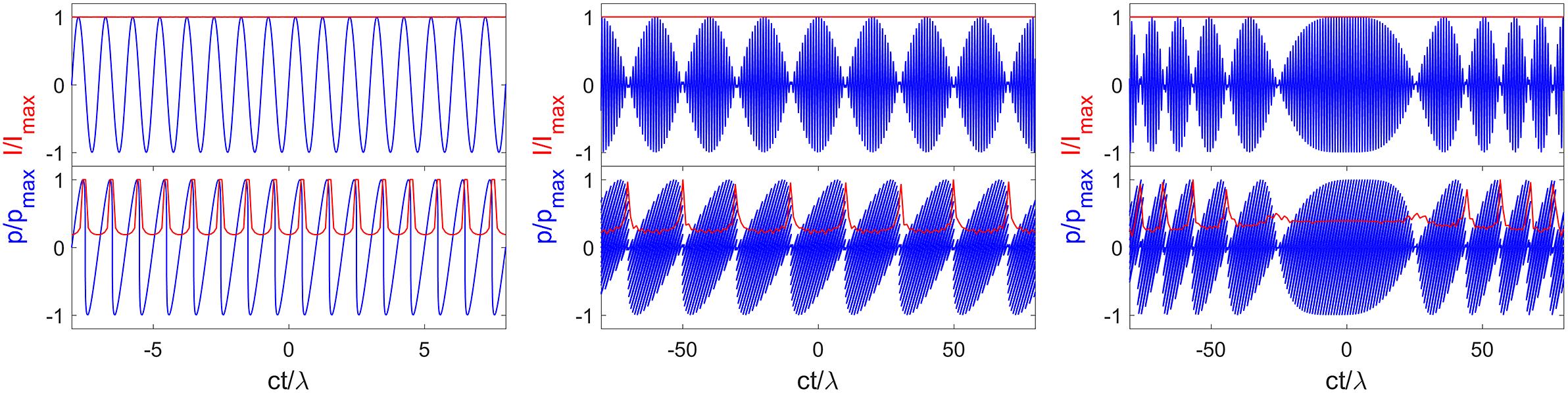
Figure 1.Longitudinal phase space of the electron beam with normal laser modulation (left), frequency beating with the unchirped laser (middle) and with the chirped laser (right).
Now we consider the frequency beating cases. The electron is transported into the modulator to interact with two unchirped lasers with the central frequencies
Furthermore, we consider the case that two linearly-chirped lasers are adopted to interact with the electron beam in the modulator with the central frequencies
The schematic layout of the proposed scheme is shown in Figure 2. In the radiator, the radiation pulse train, which reflects the longitudinal current distribution of the electron beam, is generated in the first undulator segment. The undulator length should be optimized to make the peak power high enough to suppress the shot noise but far from saturation to prevent the degradation of the electron quality. After the first delay line, the target radiation pulse is shifted forward to the upstream current peak and the microbunching (nm level) in the electron beam is washed out. Due to the unequal interval of the current spikes (several hundred nm), other radiation pulses will miss the current peak and the radiation gain processes are suppressed. The ultra-short target pulse is continuously amplified in the downstream undulator segments by repeating the above process.
![]()
Figure 2.Schematic layout of the proposed scheme.
3 Simulation
To show the performance of the proposed technique, 3D start-to-end simulations have been carried out based on the parameters of the SXFEL-HE (under design), which consists of a 3-GeV linac and two undulator lines. A high-quality electron beam with the charge of 500 pC is generated in the photoinjector and then compressed to about 1 kA in the linac with two-stage BC chicanes. The longitudinal phase space of the electron beam at the exit of the linac, simulated by the tracking code ASTRA[37] in the injector and ELEGANT[38] in the linac, is shown in Figure 3 (left). The bunch length of the electron beam is about 400 fs by the end of the linac. The normalized slice emittance is about 1.0 μm⋅rad and the slice energy spread is about 50 keV. These simulation results fit quite well with the measurements at the SXFEL facility[39,40].
![]()
Figure 3.Longitudinal phase space of the electron beam at the end of the linac (left) and at the exit of the ESASE section (right). The bunch head is to the right.
In the modulation section, a transform-limited laser pulse (longitudinal Gaussian distribution) with the central wavelength of 800 nm and pulse duration of 100 fs (full width at half maximum (FWHM)) is split and sent into two branches. The separated two optical pulses are stretched by a dispersive medium with opposite dispersions, resulting in two 1.1 ps (FWHM) long laser pulses with opposite frequency chirps. Finally, these two chirped laser pulses are sent through a splitter to recombine to a single laser pulse, as shown in the left-hand part of Figure 2, and sent into the modulator to interact with the electron beam to generate the energy modulation. The peak power of each chirped laser pulse is about 15 GW with laser waist of about 300 μm and pulse energy of about 16 mJ. The energy modulation is converted into density modulation in the downstream dispersion section, generating the gradually varied spacing pulse train. The longitudinal phase space of the electron beam at the exit of the modulation section, simulated by the 3D algorithm[41], is shown in Figure 3 (right). One can find that the peak current of about 5 kA is achieved with the current spacing of around 40 fs. The head and the tail parts of the electron beam, containing 5.1% particles in total, are cut during the simulation, which has little contribution to the radiation process but will result in the distortion of the electron beam in the longitudinal direction. Subsequently, the electron pulse train is transported to the downstream radiator.
It is worth pointing out that the longitudinal space charge effect is not negligible due to the high peak current[42,43]. The longitudinal space charge field, according to Ref. [43], could be calculated by the following:
![]()
Figure 4.Electron beam energy modulation from the longitudinal space charge field from the 39 m undulator.
Thirteen 3-m-long undulators in total are used with the period length of 30 mm. The numbers of undulators used in the first to ninth undulator segments are chosen as 3, 2, 2, 1, 1, 1, 1, 1 and 1, respectively. The simulation results are summarized in Figure 5. In the first undulator segment, an attosecond pulse train, which reflects the comb-like current distribution, is generated with the peak power of about several tens of megawatt. Then the attosecond pulse train is shifted forward in the downstream delay line, so that the target radiation pulse (the last one) can overlap the adjacent electron pulse while the others meet the low-current part of the electron beam because of the unequal interval of the current distribution. Meanwhile, the microbunching accumulated in the first undulator segment is smeared out when the beam passes through the delay line. An X-band deflecting cavity is located at the end of the undulator line with temporal resolution better than 10 fs, which helps one to choose the strength of the delay line during future experimental research. The relative temporal jitter between the laser pulses and the electron beam is only tens of femtoseconds at FEL facilities, for example, approximately 50 fs rms at SXFEL[39]. A stable comb-like structure without obvious shot-to-shot variations had been experimentally demonstrated at FERMI[45], indicating that convenient optimization methods will be feasible for the tuning of the proposed scheme. Besides, one could increase the pulse duration of the seed laser and the electron beam to further increase the tolerance of temporal jitters.
![]()
Figure 5.The output radiation evolution and the spectrum along the undulator line at the end of the first, fourth and ninth undulator segments.
In the second undulator segment, the target radiation pulse is shifted and interacts with a ‘fresh’ part of the electron beam, leading to continuous amplification, similar to the direct seeding scheme[46]. The amplification of the satellite pulses is suppressed, leading to continuous growth of the contrast, which is defined as the percentage of the target radiation pulse energy. By repeating the process of the undulator amplification and radiation delay, an isolated radiation pulse is achieved with a peak power of 330 GW and a pulse duration of about 620 as after nine undulator segments. The contrast of the target radiation pulse is over 99%. The bandwidth of the final output is about 0.5%, which is about 1.1 times that of the Fourier transform limit. The final peak power of the radiation can be further improved by optimizing the parameters of the frequency beating to generate more current spikes and employ more undulator segments. The output pulse duration can be further shortened by using shorter undulators, which helps to decrease the slippage effect.
3D simulations for SASE have also been performed, sharing the same electron beam at the end of the linac and the same undulator parameters. The comparison results are given in Figure 6. It is easy to find that the normal SASE saturates at around 35 m with the peak power of about 20 GW, which is one order of magnitude lower than that of the proposed scheme.
![]()
Figure 6.FEL gain curves for the proposed scheme and the normal SASE.
4 Conclusion
In this paper, we proposed a novel and feasible method to generate isolated attosecond radiation pulses based on the electron beam compression with optical beating technique. In the proposed method, two chirped optical lasers with the same central wavelength and opposite frequency chirps are employed to modulate the electron beam and generate the gradually varied spacing current spikes. The isolated attosecond pulse could be generated in the downstream radiator with a multi-stage amplification setup. 3D start-to-end simulations have been performed and the results show that an isolated radiation pulse at 2 nm can be achieved with the peak power of about 330 GW and pulse duration of about 620 as, with the longitudinal space charge effect and longitudinal resistive wall wakefield being taken into account. The output peak power can be further improved and the pulse duration can be shortened by optimizing the parameters of the optical laser, the electron beam and the undulators. For example, by increasing the beam energy (4 GeV) to generate shorter wavelength (1 nm) radiation and increasing durations of the laser pulses and the electron beam to get more current spikes, it is possible to further suppress the slippage effect to get shorter pulses with higher peak power. The proposed scheme is feasible and can be implemented in the existing FEL facilities. This kind of attosecond coherent X-ray light source has great potential applications in the study of ultrafast electronic phenomena.
References
[1] M. Hentschel, R. Kienberger, C. Spielmann, G. A. Reider, N. Milosevic, T. Brabec, P. Corkum, U. Heinzmann, M. Drescher, F. Krausz. Nature, 414, 509(2001).
[2] X. F. Li, A. L’Huillier, M. Ferray, L. A. Lompré, G. Mainfray. Phys. Rev. A, 39, 5751(1989).
[3] G. Sansone, E. Benedetti, F. Calegari, C. Vozzi, L. Avaldi, R. Flammini, L. Poletto, P. Villoresi, C. Altucci, R. Velotta, S. Stagira, S. DeSilvestri, M. Nisoli. Science, 314, 443(2006).
[4] F. Ferrari, F. Calegari, M. Lucchini, C. Vozzi, S. Stagira, G. Sansone, M. Nisoli. Nat. Photon., 4, 875(2010).
[5] J. M. J. Madey. J. Appl. Phys., 42, 1906(1971).
[6] W. Ackermann, G. Asova, V. Ayvazyan, A. Azima, N. Baboi, J. Bähr, V. Balandin, B. Beutner, A. Brandt, A. Bolzmann, R. Brinkmann, O. I. Brovko, M. Castellano, P. Castro, L. Catani, E. Chiadroni, S. Choroba, A. Cianchi, J. T. Costello, D. Cubaynes et al. Nat. Photon., 1, 336(2007).
[7] P. Emma, R. Akre, J. Arthur, R. Bionta, C. Bostedt, J. Bozek, A. Brachmann, P. Bucksbaum, R. Coffee, F.-J. Decker, Y. Ding, D. Dowell, S. Edstrom, A. Fisher, J. Frisch, S. Gilevich, J. Hastings, G. Hays, Z. Huang Ph. Hering et al. Nat. Photon., 4, 641(2009).
[8] T. Ishikawa, H. Aoyagi, T. Asaka, Y. Asano, N. Azumi, T. Bizen, H. Ego, K. Fukami, T. Fukui, Y. Furukawa, S. Goto, H. Hanaki, T. Hara, T. Hasegawa, T. Hatsui, A. Higashiya, T. Hirono, N. Hosoda, M. Ishii, T. Inagaki et al. Nat. Photon., 6, 540(2012).
[9] E. Allaria, R. Appio, L. Badano, W. A. Barletta, S. Bassanese, S. G. Biedron, A. Borga, E. Busetto, D. Castronovo, P. Cinquegrana, S. Cleva, D. Cocco, M. Cornacchia, P. Craievich, I. Cudin, G. D'Auria, M. Dal Forno, M. B. Danailov, R. De Monte, G. De Ninno et al. Nat. Photon., 6, 699(2012).
[10] E. Allaria, D. Castronovo, P. Cinquegrana, P. Craievich, M. Dal Forno, M. B. Danailov, G. D'Auria, A. Demidovich, G. De Ninno, S. Di Mitri, B. Diviacco, W. M. Fawley, M. Ferianis, E. Ferrari, L. Froehlich, G. Gaio, D. Gauthier, L. Giannessi, R. Ivanov, B. Mahieu et al. Nat. Photon., 7, 913(2013).
[11] H.-S. Kang, C.-K. Min, H. Heo, C. Kim, H. Yang, G. Kim, I. Nam, S. Y. Baek, H.-J. Choi, G. Mun, B. R. Park, Y. J. Suh, D. C. Shin, J. Hu, J. Hong, S. Jung, S.-H. Kim, K. H. Kim, D. Na, S. S. Park et al. Nat. Photon., 11, 708(2017).
[12] E. Prat, R. Abela, M. Aiba, A. Alarcon, J. Alex, Y. Arbelo, C. Arrell, V. Arsov, C. Bacellar, C. Beard, P. Beaud, S. Bettoni, R. Biffiger, M. Bopp, H. Braun, M. Calvi, A. Cassar, T. Celcer, M. Chergui, P. Chevtsov et al. Nat. Photon., 14, 748(2020).
[13] W. Decking, S. Abeghyan, P. Abramian, A. Abramsky, A. Aguirre, C. Albrecht, P. Alou, M. Altarelli, P. Altmann, K. Amyan, V. Anashin, E. Apostolov, K. Appel, D. Auguste, V. Ayvazyan, S. Baark, F. Babies, N. Baboi, P. Bak, V. Balandin et al. Nat. Photon., 14, 391(2020).
[14] Z. T. Zhao, D. Wang, Q. Gu, L. Yin, M. Gu, Y. Leng, B. Liu. Appl. Sci., 7, 607(2017).
[15] B. Liu, C. Feng, D. Gu, F. Gao, H. Deng, M. Zhang, S. Sun, S. Chen, W. Zhang, W. Fang, Z. Wang, Q. Zhou, Y. Leng, M. Gu, L. Yin, Q. Gu, G. Fang, D. Wang, Z. Zhao. Appl. Sci., 12, 176(2022).
[16] A. Kondratenko, E. L. Saldin. Part. Accel., 10, 207(1980).
[17] R. Bonifacio, C. Pellegrini, L. M. Narducci. Opt. Commun., 50, 373(1984).
[18] M. Fuchs, M. Trigo, J. Chen, S. Ghimire, S. Shwartz, M. Kozina, M. Jiang, T. Henighan, C. Bray, G. Ndabashimiye, P. H. Bucksbaum, Y. Feng, S. Herrmann, G. A. Carini, J. Pines, P. Hart, C. Kenney, S. Guillet, S. Boutet, G. J. Williams, M. Messerschmidt, M. M. Seibert, S. Moeller, J. B. Hastings, D. A. Reis. Nat. Phys., 11, 964(2015).
[19] A. Aquila, A. Barty, C. Bostedt, S. Boutet, G. Carini, D. dePonte, P. Drell, S. Doniach, K. H. Downing, T. Earnest, H. Elmlund, V. Elser, M. Gühr, J. Hajdu, J. Hastings, S. P. Hau-Riege, Z. Huang, E. E. Lattman, F. R N C Maia, S. Marchesin, A. Ourmazd, C. Pellegrini, R. Santra, I. Schlichting, C. Schroer, J. C. H. Spence, I. A. Vartanyants, S. Wakatsuki, W. I. Weis, G. J. Williams. Struct. Dyn., 2, 041701(2015).
[20] Y. Ding, A. Brachmann, F.-J. Decker, D. Dowell, P. Emma, J. Frisch, S. Gilevich, G. Hays, Z. Huang Ph. Hering, R. Iverson, H. Loos, A. Miahnahri, H.-D. Nuhn, D. Ratner, J. Turner, J. Welch, W. White, J. Wu. Phys. Rev. Lett., 102, 254801(2009).
[21] P. Emma, K. Bane, M. Cornacchia, Z. Huang, H. Schlarb, G. Stupakov, D. Walz. Phys. Rev. Lett., 92, 074801(2004).
[22] S. Huang, Y. Ding, Z. Huang, J. Qiang. Phys. Rev. ST Accel. Beams, 17, 120703(2014).
[23] A. A. Zholents. Phys. Rev. ST Accel. Beams, 8, 040701(2005).
[24] J. Duris, S. Li, T. Driver, E. G. Champenois, J. P. MacArthur, A. A. Lutman, Z. Zhang, P. Rosenberger, J. W. Aldrich, R. Coffee, G. Coslovich, F.-J. Decker, J. M. Glownia, G. Hartmann, W. Helml, A. Kamalov, J. Knurr, J. Krzywinski, M. Lin, J. P. Marangos et al. Nat. Photon., 14, 30(2020).
[25] T. Tanaka. Phys. Rev. Accel. Beams, 22, 110704(2019).
[26] N. S. Mirian, M. D. Fraia, S. Spampinati, F. Sottocorona, E. Allaria, L. Badano, M. B. Danailov, A. Demidovich, G. D. Ninno, S. D. Mitri, G. Penco, P. R. Ribič, C. Spezzani, G. Gaio, M. Trovó, N. Mahne, M. Manfredda, L. Raimondi, M. Zangrando, O. Plekan, K. C. Prince, T. Mazza, R. J. Squibb, C. Callegari, X. Yang, L. Giannessi. Nat. Photon., 15, 523(2021).
[27] D. Gauthier, E. Allaria, M. Coreno, I. Cudin, H. Dacasa, M. B. Danailov, A. Demidovich, S. D. Mitri, B. Diviacco, E. Ferrari, P. Finetti, F. Frassetto, D. Garzella, S. Künzel, V. Leroux, B. Mahieu, N. Mahne, M. Meyer, T. Mazza, P. Miotti et al. Nat. Commun., 7, 13688(2016).
[28] N. R. Thompson, B. W. J. McNeil. Phys. Rev. Lett., 100, 203901(2008).
[29] T. Tanaka. Phys. Rev. Lett., 110, 084801(2013).
[30] R. Bonifacio, L. De Salvo Souza, P. Pierini, N. Piovella. Nucl. Instrum. Methods Phys. Res. Sect. A, 296, 358(1990).
[31] R. Bonifacio, N. Piovella, B. W. J. McNeil. Phys. Rev. A, 44, R3441(1991).
[32] Z. Wang, C. Feng, Z. Zhao. Phys. Rev. Accel. Beams, 20, 040701(2017).
[33] T. Tanaka, Y. W. Parc, Y. Kida, R. Kinjo, C. H. Shim, I. S. Ko, B. Kim, D. E. Kim, E. Prat. J. Synchrotron Rad., 23, 1273(2016).
[34] Z. Zhao, K. J. Leedle, D. S. Black, O. Solgaard, R. L. Byer, S. Fan. Phys. Rev. Lett., 127, 164802(2021).
[35] R. Akre, D. Dowell, P. Emma, J. Frisch, S. Gilevich, G. Hays, P. Hering, R. Iverson, C. Limborg-Deprey, H. Loos, A. Miahnahri, J. Schmerge, J. Turner, J. Welch, W. White, J. Wu. Phys. Rev. ST Accel. Beams, 11, 030703(2008).
[36] H. Zhang, W. Wang, S. Jiang, C. Li, Z. He, S. Zhang, Q. Jia, L. Wang, D. He. J. Instrum., 16, P08019(2021).
[37] http://tesla.desy.de/~meykopff/. http://tesla.desy.de/~meykopff/
[38] M. Borland. , “ELEGANT: A flexible SDDS-compliant code for accelerator simulation,” Advanced Photon Source LS-287 ().(2000).
[39] C. Feng, T. Liu, S. Chen, K. Zhou, K. Zhang, Z. Qi, D. Gu, Z. Wang, Z. Jiang, X. Li, B. Wang, X. Wang, W. Zhang, L. Feng, C. Li, T. Lan, B. Li, M. Zhang, H. Deng, D. Xiang, B. Liu, Z. Zhao. Optica, 9, 785(2022).
[40] L. Zeng, C. Feng, D. Gu, X. Wang, K. Zhang, B. Li, Z. Zhao. Fundam. Res., 2, 929(2022).
[41] L. Zeng, C. Feng, X. Wang, K. Zhang, Z. Qi, Z. Zhao. Photonics, 7, 117(2020).
[42] G. Geloni, E. Saldin, E. Schneidmiller, M. Yurkov. Proceedings of FEL 2007(2007).
[43] Y. Ding, Z. Huang, D. Ratner, P. Bucksbaum, H. Merdji. Phys. Rev. ST Accel. Beams, 12, 060703(2009).
[44] S. Reiche. Nucl. Instrum. Methods Phys. Res. Sect. A, 429, 243(1999).
[45] E. Roussel, E. Ferrari, E. Allaria, G. Penco, S. Di Mitri, M. Veronese, M. Danailov, D. Gauthier, L. Giannessi. Phys. Rev. Lett., 115, 214801(2015).
[46] G. Lambert, T. Hara, D. Garzella, T. Tanikawa, M. Labat, B. Carre, H. Kitamura, T. Shintake, M. Bougeard, S. Inoue, Y. Tanaka, P. Salieres, H. Merdji, O. Chubar, O. Gobert, K. Tahara, M.-E. Couprie. Nat. Phys., 4, 296(2008).


Set citation alerts for the article
Please enter your email address

© Copyright 2018-2021 | Chinese Laser Press. All Rights Reserved 沪ICP备15018463号-20