
Karim Achouri, Ville Tiukuvaara, Olivier J. F. Martin. Spatial symmetries in nonlocal multipolar metasurfaces[J]. Advanced Photonics, 2023, 5(4): 046001
- Advanced Photonics
- Vol. 5, Issue 4, 046001 (2023)
Abstract
1 Introduction
Over the past few years, metasurfaces have gained increasing attention due to their low form factor and incredible light-control capabilities. As a consequence, we have seen a plethora of promising applications emerge, such as light refraction,1 polarization control,2 and holography.3 Naturally, this has further sparked an increasing interest towards ever more advanced applications, such as optical analog processing using nonlocal interactions4,5 or sensing, detection, and polarization multiplexing using chirality.6
These advances have prompted the need for appropriate modeling approaches able to predict the electromagnetic behavior of a metasurface so as to leverage the adequate available degrees of freedom that they offer for an optimal implementation of the desired specifications or simply to achieve higher performance. Conveniently, several metasurface modeling techniques have been proposed throughout the years,11
However, despite being generally powerful, these techniques have been shown to be limited when it comes to modeling the angular scattering properties of a metasurface.20,21 This is particularly a problem for applications pertaining to optical analog signal processing, where accurate angular scattering control over a large range of incidence angles is crucial.4,5 One of the main reasons for such a limitation is the fact that optical metasurfaces have unit cells that are relatively large compared to the wavelength, especially those based on dielectric resonators, implying that multipolar contributions beyond the dipolar regime start contributing significantly to their scattering response.21 Since multipolar components, such as dipoles and quadrupoles, have different angular scattering behaviors,22
Sign up for Advanced Photonics TOC. Get the latest issue of Advanced Photonics delivered right to you!Sign up now
While multipolar metasurface modeling techniques exhibit promising features in terms of improved modeling accuracy and better physical insight into the scattering process, they also pose a challenging problem. Compared to dipolar modeling, the inclusion of the required nonlocal third and fourth rank effective material tensors introduces a significant number of additional degrees of freedom and makes the practical application of the modeling significantly more difficult and cumbersome. Nevertheless, this problem may be mitigated by considering that many of these degrees of freedom do not play a role in most conventional metasurfaces and can thus be neglected. For instance, parameters that are related to polarization rotation should not be taken into account for metasurfaces that do not induce polarization rotation. Knowing which parameters should or should not be included in the model may be decided, in the most simple cases, just by intuitive reasoning, which has been a common practice in the case of dipolar metasurfaces.16 For slightly more complicated cases, for instance, those that require bianisotropic responses, it is possible to determine which are the dominant parameters that should be considered using a series of numerical simulations with a complex scheme of illumination conditions.33
On the other hand, the use of chiral responses in metasurfaces for sensing, polarization control, or asymmetric transmission applications has led to fascinating works investigating the origins of such responses. It was, for instance, shown that 3D geometrically chiral structures are not necessary to achieve chiral responses.36
In this work, our goal is to address these two requirements, namely, to devise a method to determine the existence of multipolar components and that of chiral responses (or other peculiar scattering effects) in the case of an arbitrary metasurface. To this end, we propose to establish a connection between the spatial symmetries of a metasurface and its effective material parameters, as well as its scattering response.
Clearly, the idea of drawing such a connection is not new, as many works have already proposed using spatial symmetries to model metamaterials. For instance, concepts pertaining to group theory have been leveraged to associate the point group of a metasurface to its dipolar material parameters51,52 or to predict the existence of certain responses based on the symmetries of the metamaterial structure.53
Based on the existing literature, we aim at providing a simple, straightforward, and coherent framework that connects the symmetries, material tensors, and scattering response of a metasurface in a way that does not require an extensive knowledge of group theory. Thus, the proposed approach only requires listing the spatial symmetries of a metasurface, which makes it accessible to the largest possible audience. It also does not require performing any complicated numerical simulation, which makes it fast and simple to use. In addition, this framework extends the existing methods by including the presence of quadrupolar and nonlocal responses, which is crucial for properly modeling certain types of chiral responses, as we shall see. Finally, we will not restrict ourselves to the study of chiral responses but instead investigate the complete scattering response of a metasurface by computing its full scattering matrix. To facilitate the use of the proposed framework, we also provide a Python script, which is accessible on GitHub,78 and that simply requires listing the spatial symmetries of the metasurface. Finally, it should be noted that while we concentrate our attention on the topic of metasurfaces, the formalism developed thereafter also applies to 3D metamaterials, providing that they can be homogenized so that their electromagnetic response may be model via effective material parameters.
This paper is organized as follows. In Sec. 2.1, we review the general approach for transforming the dipolar material parameters of a metasurface according to an arbitrary spatial symmetry, which is a crucial step for ultimately obtaining the material parameters corresponding to the metasurface. In Sec. 2.2, we extend that approach to multipolar responses and, in Sec. 2.3, finally show how to connect spatial symmetries and multipolar material parameters. In Sec. 3, we connect the spatial symmetries of a metasurface and the fields that interact with it to its corresponding scattering matrix. Finally, in Sec. 4, we provide three examples illustrating the application of the proposed framework.
2 Material Tensors and Symmetries
The general approach for connecting the effective material tensors of a metasurface to its spatial symmetries is based on Neumann’s principle.79
We shall next review the conventional method used to derive such invariance conditions in the case of a medium described by dipolar responses. Then, we will extend these conditions to the case of multipolar responses.
It should be noted that throughout this work, we shall consider that a metasurface is an electrically thin array consisting of a subwavelength periodic arrangement of reciprocal scattering particles. The period of the array is considered small enough compared to the wavelength so that no diffraction orders exist (besides the zeroth orders in reflection and transmission), irrespective of the direction of wave propagation and the refractive index of the background media. Under these assumptions, it follows that the electromagnetic response of such a metasurface can be modeled as that of a homogeneous and uniform sheet of effective material parameters.16,82
2.1 In the Case of Dipolar Responses
Let us consider a uniform and homogeneous bianisotropic metasurface whose constitutive relations are given as83
To obtain the invariance conditions that apply to parameters , , , and in Eq. (1), we must first understand how the electric and magnetic fields, and , transform under a given symmetry operation. For this purpose, consider the transformation matrix , that corresponds to an arbitrary symmetry operation such as those described in Appendix. It follows that and , respectively, transform into and as51,52
We next use Eqs. (3) and (4) to obtain the transformation relations that apply to the material parameters in Eq. (1). To do so, we reverse Eqs. (3) and (4) to express , , , and in terms of , , , and , respectively and then substitute the resulting relations into Eq. (1). By association, this readily yields51
The relations in Eq. (5) represent how dipolar material parameters change under a particular spatial transformation defined by . We shall see in Sec. 2.3 how such relations may be transformed into symmetry invariance conditions but, first, we shall investigate how these relations may be extended to an arbitrary multipolar order, which is the topic of the next section.
2.2 Extension to Multipolar Responses
As we shall see in Sec. 4, some electromagnetic effects cannot be described solely using a purely dipolar model. This motivates the need to extend the dipolar framework discussed in the previous section to include higher-order multipolar components and their associated spatially dispersive responses. For this purpose, we combine concepts from the multipolar theory typically used for modeling metamaterials22
It follows that the quadrupolar constitutive relations read21,31,64
As was done in Eq. (5), we may express the transformation relations that apply to the parameters in Eq. (7). To do so, we make use of tensor notation (in what follows, we omit the summations over repeated indices for convenience), since it applies more conveniently to the third- and fourth-order tensorial parameters in Eq. (7). It follows that an arbitrary tensor , corresponding to any of the tensorial parameters of orders 1 to 4 in Eq. (7), transforms under the transformation as84
Extending this formalism to higher-order multipolar contributions is rather trivial. To do so, one first needs to include these additional contributions in Eq. (7) along with their corresponding spatial derivatives, which increases the total number of spatially dispersive material parameter tensors. For instance, taking into account octupolar contributions would require adding 20 new material tensors of orders 4 to 6 in Eq. (7), since second-order spatial derivatives must be included. Then, the relations in Eq. (8) would also need to be extended to apply to the additional material tensors of orders 5 and 6, which can be easily achieved by logical extrapolation.
2.3 Invariance Conditions for Material Tensors
We have just established that under a given symmetry operation, the material parameters in Eq. (7) transform according to the relations in Eq. (8). We are now interested in connecting the material parameters in Eq. (7) to the spatial symmetries of a metasurface. This may be achieved by considering that, according to Neumann’s principle, if a given structure is invariant under a symmetry operation, then its material parameters should also be invariant under the same operation.79
To obtain the material parameters that correspond to a given metasurface structure, we shall now describe a technique directly based on Eq. (9). This technique differs from those described in the literature, such as those that consist in expressing the material parameters for various symmetry groups51,52 or those using the orthogonality theorem to find the irreducible representation of the structure.53
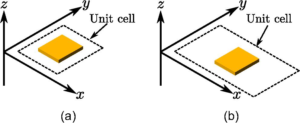
To illustrate this process, let us consider two different metasurfaces formed by periodically arranging in the plane either the unit cell shown in Fig. 1(a) or the one shown in Fig. 1(b). These two unit cells are composed of the same scattering particle and only differ in the geometry of their lattice.
![]()
Figure 1.Two different metasurface unit cells made of identical scattering particles arranged within (a) a square lattice and (b) a rectangular lattice.
Inspecting the symmetries of these two metasurfaces, it is obvious that both are invariant under reflections through the , , and axes, which corresponds to the symmetry operations (see Appendix). However, although they are composed of the same scattering particle, the metasurface unit cell in Fig. 1(a) possesses a square lattice, whereas the one in Fig. 1(b) possesses a rectangular lattice. It follows that these two metasurfaces do not exhibit the same rotation symmetry along the axis. Indeed, a metasurface composed of a periodic arrangement of the unit cell in Fig. 1(a) would have a rotation symmetry [corresponding to 90 deg rotation symmetry along ; see Eq. (33)], whereas the one composed of the unit cell in Fig. 1(b) would have a rotation symmetry (corresponding to 180 deg rotation symmetry along ).
Now that we have found the symmetries corresponding to the two metasurfaces in Fig. 1, we can apply the process described above to find the permittivity matrix of these structures. Here, we restrict ourselves to finding for simplicity but without loss of generality, since the process to obtain the other material parameters in Eq. (7) would be identical. We provide more complete examples that include all material parameters in Sec. 4.
The process of finding the permittivity matrix corresponding to the metasurfaces in Fig. 1 starts by considering the full permittivity matrix given as
This process is then repeated by solving Eq. (9b) again, but this time with Eq. (11) and , and then once again with to obtain
We are now left with the two rotation symmetries, and . However, it turns out that the permittivity matrix in Eq. (12) already corresponds to the structure in Fig. 1(b). Indeed, we do not even need to apply a further iteration of the process with because a structure possessing reflection symmetries along the and axes necessarily and automatically possesses a rotation symmetry. (However, the opposite is not necessarily true. Indeed, a structure possessing a symmetry, such as an S-shaped structure lying in the plane, would not possess a reflection symmetry along the axis.) This would therefore make a further application of the process with redundant. On the other hand, the rotation symmetry is not redundant and applying Eq. (19) with and Eq. (9b) leads to
Obviously, for such simple structures as those in Fig. 1, the results obtained in Eqs. (12) and (13) could have been guessed simply based on intuition. However, for more complex structures, intuition alone is usually not sufficient to guess the correct shape of the material parameter tensors, especially those related to quadrupolar responses in Eq. (7). The usefulness of the approach in such cases is emphasized using examples found later in Sec. 4.
Note that the background medium is assumed to be identical on both sides of the metasurfaces in Fig. 1. However, in practice, the scattering particles are usually deposited on top of a substrate instead of being embedded into a uniform background medium. In this case, the presence of the substrate would actually break the symmetry of the system in the direction, meaning that the metasurface response would not be invariant under . While this would not change the shape of the permittivity matrices in Eqs. (12) and (13), it would have significant influence on the other material parameters in Eq. (7). For instance, it has been shown that the presence of a substrate is sufficient to lead to 3D chiral responses for metasurfaces composed of only 2D chiral scattering particles such as Gammadion structures.41
3 Scattering Matrix from Symmetries
In the previous sections, we have seen how the effective material tensors of a metasurface may be predicted by considering the spatial symmetries of the metasurface unit cell. We shall now investigate the relationships between the scattering properties of a metasurface and its spatial symmetries.
It turns out that the spatial symmetries of the metasurface unit cell are not the only parameters to consider when investigating the metasurface scattering response. Indeed, one needs to also take into account the influence of the waves interacting with the metasurface. This is because the combined system composed of the superposition of the metasurface and the incident and scattered waves exhibits spatial symmetries that are not the same as those of the metasurface alone.70
In what follows, we shall review the general concepts discussed in Refs. 72 and 73 for the case of reciprocal metasurfaces and develop a procedure to obtain the scattering matrix of a metasurface for a given direction of propagation that is similar to the procedure described in Sec. 2.3.
Let us first consider the case of a reciprocal metasurface illuminated by obliquely propagating plane waves. Since the metasurface is considered to be uniform and its lattice period is deeply subwavelength, it scatters the incident waves according to Snell’s law. Such a situation is depicted in Fig. 2, where two input and output “ports” transmit and receive, respectively, TE- and TM-polarized waves. Here, the plane of incidence is arbitrarily chosen to be the plane. The scattering matrix associated with the interactions in Fig. 2 is given as72,73
![]()
Figure 2.Cross-sectional view of a metasurface interacting with TE- and TM-polarized plane waves.
We are now looking for an invariance condition that would apply to in a similar way that the invariance conditions in Eq. (9) applied to the material tensor . For this purpose, we need to relate to the symmetries of the combined system (metasurface and direction of wave propagation) defined by . From that prospect, we start by defining a rotated version of that is aligned with the orientation of the plane of incidence, since the latter is generally not restricted to the plane. This rotated version of is given as
Now, since we are considering a given plane of incidence, it follows that only the spatial symmetries that map an input/output port to another one are to be considered for obtaining a symmetry-invariant scattering matrix.73 The other symmetry operations, such as the rotation symmetry, should not be considered, since they would be inconsistent with a fixed plane of incidence. Therefore, the only spatial symmetries that make sense to be taken into account are and , where as well as the inversion symmetry operation defined by .
Among this set of relevant symmetry operations, we may further classify them according to their effects on the polarization and the direction of wave propagation of the incident and scattered waves. For instance, applying the symmetry operation on the system in Fig. 2 would flip the sign of the TM polarizations while leaving the TE polarizations unaffected, and it would also flip the direction of the propagation vectors . On the other hand, the operation would flip the sign of the TE polarizations while leaving both the TM polarizations and the -vectors unchanged.
Finally, we need to define a transformation operation that would apply to in the same way that the tensor was transformed by the operation in Eq. (8). This may be achieved by defining the transformed scattering matrix, , as , where is a transformation matrix that is related to .73 Note that in Ref. 73 a specific transformation matrix was defined for each of the relevant symmetry operations specified previously, based on the intuitive effects that these operations have on the polarizations and propagation directions of the waves. In what follows, we shall instead provide a technique that directly connects with .
Noting that the invariance condition may be expressed as for the symmetry operations that do not affect the direction of the vectors, whereas it is given by for the symmetry operations that flip the vectors,73 we define the general invariance condition as
The transformation matrix in Eq. (16) is now obtained by generalizing the results provided in Ref. 73, which leads to
The procedure to obtain the scattering matrix of a given metasurface under oblique incidence is quite similar to the approach described in Sec. 2.3 for finding the metasurface material parameter tensors. It consists in first defining the orientation of the plane of incidence with , and then recursively solving Eq. (16) for each of the relevant symmetry operations expressed using Eq. (15).
For the special case of normally incident plane waves impinging on the metasurface, it is required to slightly modify this procedure.72 First, at normal incidence, the orientation of the plane of incidence loses its meaning and Eq. (15) should be bypassed by setting . Then, the TE and TM polarizations should now be associated with and polarizations, respectively. Finally, it now actually makes sense to consider the rotation symmetry as it correctly maps TE to TM polarizations together. For this specific symmetry operation, the invariance condition Eq. (16) reduces to with given as72
For all the other symmetry operations, relations Eqs. (16)–(19) should be used.
Before looking at examples illustrating the application of the method described above, which will be presented in the next section, we would like to comment on how to deduce the polarization effects induced by a metasurface directly from its scattering matrix. Considering the general scattering matrix [Eq. (14)], we see that it may be reduced to four internal submatrices composed of two sets of reflection and transmission matrices. Each one of these submatrices may be associated with a Jones matrix, since they describe how different polarizations are scattered by the metasurface.85 From a given Jones matrix, it is then possible to deduce the general effect that the metasurface has on different polarization states.75
| Jones matrix | ||||||
| Polarization effects | None | LP biref. | LP biref. polarization conversion asymmetric transmission | CP biref.polarization rotation | LP/CP biref.polarization conversion | LP/CP biref. polarization conversion asymmetric transmission |
Table 1. Jones matrices and their effects on the polarization state.75
4 Illustrative Examples
We shall now look at three examples that illustrate the application of the techniques described in Sec. 2 and in Sec. 3. In these examples, we will represent the material parameter tensors in way that is reminiscent of how they are depicted in Ref. 34, meaning that we will make use of the fact that the quadrupolar tensors in Eq. (6) are assumed to be irreducible tensors (symmetric and traceless), which allows us to greatly reduce the number of independent components in Eq. (7). This also means that the derivative operators in Eq. (7) can be simplified such that, for instance, the electric field gradient becomes34
4.1 Extrinsic Chirality
Extrinsic chirality corresponds to an electromagnetic effect in which a medium (in our case a metasurface) exhibits a chiral response even though it is not composed of geometrically 3D chiral scattering particles.43
Consider the metasurface unit cell depicted in Fig. 3 composed of a T-shaped metallic particle embedded in a uniform background medium. The metasurface is illuminated by an obliquely incident plane wave propagating either in the plane, as in Fig. 3(a), or in the -plane, as in Fig. 3(b).
![]()
Figure 3.(a) and (b) Metasurface unit cell composed of a T-shaped particle being illuminated by an obliquely incident plane wave. The metasurface lattice is a square.
The spatial symmetries of the metasurface, assuming that it has a square lattice, are directly found to be and . Note that it also exhibits a rotation symmetry; however, it is redundant, since we have already considered its reflection symmetry, as explained in Sec. 2.3. Applying the procedure outlined in Sec. 2.3, we find the multipolar components of this metasurface and present them in Fig. 4, using Eq. (21), in way that is similar to the representations in Ref. 34.
![]()
Figure 4.Representation of the symmetry-allowed multipolar components corresponding to the metasurface in
In Fig. 4, the vertical and the horizontal axes, respectively, correspond to the multipolar densities and the excitation vector, on the left- and right-hand side of Eq. (7), where the term corresponds to the first element in Eq. (21), and so on. The numbers and the colors in the figure are purely arbitrary and only help visualize which components are allowed to exist due to the symmetries of the structure and which components are related to each other (components that have the same number and color).
The information provided in Fig. 4 reveals the complexity of the metasurface multipolar response, notably its bianisotropic dipolar nature due to the existence of the components numbered 4 and 5 in the matrix. Comparing the results in Fig. 4 with those of the dolmen structure provided in Ref. 34 reveals a perfect match between the two methods. It should be noted that results in Fig. 4 only correspond to the components that are allowed to exist, and it does not provide any information about the magnitude of these components. On the other hand, the results presented in Ref. 34 provide the numerical value of the multipolar components, since the method used to obtain them consists in numerically simulating the structure with a complex set of different illumination conditions, which results in an important computational cost.
Now, we use the approach described in Sec. 2 to compute the scattering matrix for the obliquely propagating waves of Fig. 3. Using Eqs. (15)–(19) with , , and yields the scattering matrix, for the case in Fig. 3(a), given as
Similarly, using , we obtain the scattering matrix for the case in Fig. 3(b) as
Comparing Eqs. (22) and (23), it is clear that illuminating the metasurface along different directions of wave propagation leads to quite different polarization effects. When the metasurface is illuminated in the plane, as in Fig. 3(a), we see that the internal Jones matrices in Eq. (22) exhibit circular birefringent properties typical of chiral responses (see Table 1). On the other hand, illuminating the metasurface in the plane, as in Fig. 3(b), leads to a linear birefringent response, as evidenced by the scattering matrix in Eq. (23). This analysis confirms that the metasurface is extrinsically chiral, since its chiral response is dependent on the direction of wave propagation.
One way to understand the emergence of a chiral response in this structure is to consider its bianisotropic dipolar response. For an illumination in the plane, both TE and TM polarizations excite the components 4 and 5 in Fig. 4, which correspond to the components and in Eq. (7), respectively, or to their reciprocal counterparts and . Since these two components have different values that thus cannot cancel each other, they lead to a net chiral response.10 However, for an illumination in the plane, both TE and TM polarizations excite either the set of parameters and or the set and , respectively. Since by reciprocity [see Eq. (2)], and , these two contributions cancel each other, leading to an absence of chiral response.
4.2 Asymmetric Angular Transmittance
We are now interested in designing a metasurface that exhibits an asymmetric angular transmittance when illuminated in the plane. While it has been shown that asymmetric angular transmittance may be achieved using spatially varying metasurfaces with phase-gradient modulations,87 we are instead interested in designing a uniform metasurface whose asymmetric scattering response stems from the asymmetry of its structure.
Let us consider the two metasurfaces depicted in Fig. 5, composed of a periodic array of L-shaped scattering particles. In Fig. 5(a), the structures lie flat on the plane of the surface, whereas they stand vertically in Fig. 5(b).
![]()
Figure 5.Two metasurfaces composed of (a) planar L-shaped structures and (b) vertical L-shaped structures. In both cases, the structures have arms of equal length.
Since both structures are asymmetric in the direction, one may a priori expect that they would both lead to an asymmetric scattering response for waves propagating in the plane in opposite directions, like the waves and in Fig. 5. However, that is not the case, as we shall next demonstrate.
The spatial symmetries of the structure in Fig. 5(a) are and , whereas those of the structure in Fig. 5(b) are and , where and refer to symmetries with respect to the 45 deg diagonal between the and axes or between the and axes, respectively. These symmetries may be defined by combining those provided in the Appendix so that and . Applying the approach discussed in Sec. 2.3 to these two sets of symmetries yields their corresponding material parameter tensors, which are provided in Fig. 6. As can be seen, both structures are bianisotropic and, if one only considers their permittivity matrix, we see that and for the flat L-shaped structures of Fig. 5(a), whereas and for the vertical L-shaped structures of Fig. 5(b), as may be expected intuitively.
![]()
Figure 6.Symmetry-allowed material parameter tensors corresponding to the metasurface in (a)
We next compute their respective scattering matrices. For the case in Fig. 5(a), and the waves and that propagate in the plane (), we have
Interestingly, we see that this structure exhibits a form of extrinsic chirality similar to the one in Fig. 3(a). However, this metasurface does not possess an asymmetric angular transmittance, since the two transmission submatrices in Eq. (24) are equal to each other, implying that and transmit through the metasurface identically.
Note that if the plane of incidence coincides with the in-plane axis of symmetry along which is satisfied, as it is the case for the wave in Fig. 5(a), the extrinsic chiral response disappears, as evidenced by the scattering matrix (),
For the metasurface in Fig. 5(b), and the waves and that propagate in the plane (), we have
This time, not only is there no cross-polarized scattering, but the two transmission submatrices are different from each other ( and ), implying that the waves and interact differently with the metasurface. This indicates that asymmetric angular transmittance is possible in this situation. For the incident wave that propagates in the plane, there is, however, no co-polarized angular transmittance asymmetry, as evidenced by its scattering matrix (),
Nevertheless, illuminating the metasurface under this direction of propagation should induce a form of asymmetric transmittance when illuminated in the or the directions. This therefore does not correspond to the sought-after asymmetric angular transmittance effect.
4.3 Multipolar Extrinsic Chirality
The last example investigates the scattering response of the two metasurfaces depicted in Fig. 7 under normal illumination. The metasurface in Fig. 7(a) consists of a simple periodic array of square-shaped scattering particles, whereas the one in Fig. 7(b) is made of Gammadion structures. In both cases, the metasurface is embedded within a uniform medium.
![]()
Figure 7.Two metasurfaces composed of a periodic array of (a) square particles and (b) Gammadion particles.
While it is intuitive to guess that a normally incident plane wave impinging on the metasurface in Fig. 7(a) would not undergo polarization conversion, it is less trivial to intuitively predict the response of the metasurface in Fig. 7(b). Referring to the literature, it was for instance suggested in Ref. 41 that such an ideal Gammadion array should not exhibit a chiral response unless the scattering particles are asymmetric in the direction (or the metasurface lies on a substrate). In what follows, we shall see that the problem is in fact more complex than it appears.
Let us first compute the material parameter tensors of these two metasurfaces. The symmetries associated with the metasurface in Fig. 7(a) are , , , and , whereas those for the metasurface in Fig. 7(b) are only and . The corresponding material parameter tensors are given in Fig. 7. Inspecting the differences between Figs. 8(a) and 8(b) reveals a striking feature: they both exhibit identical purely dipolar responses, i.e., the four submatrices relating and to and are the same for both metasurfaces. This means that a modeling approach solely based on Eq. (1) would fail to predict a difference in the scattering response of these metasurfaces. It is only by considering quadrupolar responses and higher-order spatially dispersive effects that the differences between these metasurfaces become evident.
![]()
Figure 8.Symmetry-allowed material parameter tensors corresponding to the metasurface in (a)
Following the approach described in Sec. 3 for normally incident waves, the scattering matrix of the metasurface in Fig. 7(a) is given as
As may be expected, the metasurface in Fig. 7(a) is isotropic and does not induce any polarization rotation or conversion at normal incidence. On the other hand, the shape of the scattering matrix of Eq. (29) reveals that the metasurface in Fig. 7(b) should exhibit a chiral response. This may come as a surprise, considering that the metasurface is not made of geometrically 3D chiral structures and that it is illuminated at normal incidence. However, a detailed inspection of the material parameter tensors in Fig. 8(b) helps us understand why such a chiral response exists.
Consider an -polarized normally incident plane wave impinging on the metasurface in Fig. 7(b) with an electric field defined by and a magnetic field given by , with and being the wavenumber and impedance of the background medium. This wave excites the components 5 and 19 in Fig. 8(b) via the field derivatives and , which, in this case, correspond to and , respectively. Since these spatial derivatives are not zero for the considered excitation, it follows that these two material components, which do not exist for the metasurface in Fig. 7(a), respectively induce an -polarized magnetization of the metasurface, , and a -polarized polarization, , suggesting rotation of polarization. By reciprocity,64 the components 5 and 19 also induce the quadrupolar responses and that are excited via the field components and , respectively, and that also contribute to rotation of polarization.
In order to verify that the multipolar components , , , and are indeed excited when illuminating such a structure with an -polarized normally propagating plane wave, we have numerically simulated an isolated Gammadion particle. From its scattered fields, we have extracted its spherical multipolar components following the approach provided in Ref. 88. The resulting simulations are plotted in Fig. 9, where the solid and dashed lines correspond to the co- and cross-polarized multipolar components, respectively. It is thus clear that a cross-polarized response is achieved, although it is small compared to the co-polarized one. This confirms that the metasurface in Fig. 7(b) exhibits a chiral response, as suggested by its scattering matrix, Eq. (29).
![]()
Figure 9.Simulated spherical dipolar and quadrupolar components of an isolated gold Gammadion structure illuminated by an
This type of chiral response slightly differs from the one discussed in Sec. 4.1, where the chirality was due to an obliquely propagating wave interacting with the bianisotropic effective material parameters of the structure. In the case of the metasurface in Fig. 7(b), the chiral response is due to multipolar and spatially dispersive components excited by a normally propagating plane, thus indicating the presence of multipolar extrinsic chirality. The extrinsic nature of this chiral response is here not directly related to the direction of wave propagation, as it was the case in Sec. 4.1, but rather to the gradient of the fields.
5 Conclusions
We have established a relationship between the spatial symmetries of a metasurface and its corresponding material parameter tensors and scattering matrix. This relationship has been obtained based on a simple approach that consists in the recursive application of invariance conditions, instead of relying on complicated concepts pertaining to group theory. This makes this approach versatile and accessible to a large audience. Moreover, to facilitate the application of the proposed approach, we have implemented a Python script that conveniently computes the form of the material parameter tensors and the scattering matrix directly from a list of specified symmetries. This Python script is freely accessible on GitHub.78
Based on this approach, we have shown how easy it is to investigate responses such as extrinsic chirality or asymmetric angular transmittance. We have also demonstrated the possibility of multipolar extrinsic chirality, where chiral responses may be achieved in achiral structures even for normally incident waves due to the excitation of multipolar components; this was shown to result from the sensitivity of certain structures to field gradients. These examples demonstrate that intuition alone is insufficient to predict the effective material tensors and rich scattering behavior that can be achieved, and thus highlight the usefulness of our method.
6 Appendix: Symmetry Operations
Reflection symmetries may be expressed using the Householder equation89
On the other hand, the 3D rotation matrices are defined as
These matrices may be used to define the symmetry operation as
Karim Achouri received his BSc and his MSc degrees in photonics from Swiss Federal Institute of Technology in Lausanne (EPFL), in 2010 and 2012, respectively. In 2017, he received his PhD in electromagnetics from Ecole Polytechnique de Montréal. In 2017, he joined the Nanophotonics and Metrology Laboratory at EPFL as a postdoctoral fellow. His research interests are in the areas of electromagnetics, metamaterials, applied optics, photonics, and nanotechnologies.
Ville Tiukuvaara received his BEng. degree in engineering physics and his MASc. from Carleton University, Ottawa, Canada, in 2019 and 2021, respectively. Currently, he is pursuing a PhD in photonics at Swiss Federal Institute of Technology in Lausanne (EPFL), Switzerland, with a research interest in metamaterials, along with analytical and computational electromagnetics.
Olivier J. F. Martin conducts a comprehensive research that combines the development of numerical techniques, advanced nanofabrication, and experiments on plasmonic systems. Applications of his research include optical antennas, metasurfaces, nonlinear optics, optical nano-manipulations, heterogeneous catalysis, security features, and optical forces at the nanoscale. He has authored over 300 journal articles and holds a handful of patents and invention disclosures.
References
[7] M. Hentschel et al. Chiral plasmonics. Sci. Adv., 3, e1602735(2017).
[10] Y. Chen et al. Multidimensional nanoscopic chiroptics. Nat. Rev. Phys., 4, 113-124(2021).
[16] K. Achouri, C. Caloz. Electromagnetic Metasurfaces: Theory and Applications(2021).
[23] R. E. Raab, O. L. De Lange. Multipole Theory in Electromagnetism: Classical, Quantum, and Symmetry Aspects, with Applications, 128(2005).
[24] S. Mühlig et al. Multipole analysis of meta-atoms. Metamaterials, 5, 64-73(2011).
[25] S. Nanz, C. Rockstuhl. Toroidal Multipole Moments in Classical Electrodynamics(2016).
[29] S. Tretyakov et al. Electromagnetics of Bianisotropic Materials: Theory and Applications(2001).
[30] V. Agranovich. Crystal Optics with Spatial Dispersion, and Excitons(1984).
[31] C. Simovski. Composite Media with Weak Spatial Dispersion(2018).
[59] R. R. Birss. Macroscopic symmetry in space-time. Rep. Prog. Phys., 26, 307-360(1963).
[76] S. Kruk, I. Brener, Y. Kivshar et al. 5 - Tailoring transmission and reflection with metasurfaces. Dielectric Metamaterials, 145-174(2020).
[78] Spatial symmetries in multipolar metasurfaces.
[79] W. Voigt. Lehrbuch der kristallphysik (mit ausschluss der kristalloptik)(1910).
[82] S. Tretyakov. Analytical Modeling in Applied Electromagnetics(2003).
[83] J. A. Kong. Electromagnetic Wave Theory(1986).
[84] W. J. Thompson. Angular Momentum: An Illustrated Guide to Rotational Symmetries for Physical Systems(1994).
[85] . Fundamentals of Photonics(2019).
[89] A. Householder. The Theory of Matrices in Numerical Analysis(1964).

Set citation alerts for the article
Please enter your email address
© Copyright 2018-2021 | Chinese Laser Press. All Rights Reserved 沪ICP备15018463号-20