Department of Optoelectronic Information Science and Technology, School of Science, Changchun University of Science and Technology, Changchun 130022, China
Shu-bo HU, Ya-meng XU, Jia-xuan LI, Mei KONG. Simultaneous Low Nonlinearity and High Power Confinement in Slot Waveguides[J]. Acta Photonica Sinica, 2020, 49(2): 0213002
Copy Citation Text
The effects of the slot waveguide structure and cladding material on the nonlinearity and the power confinement were systematically investigated by using the full vectorial model of the nonlinear effect and the finite element mode solver of the slot waveguide. The results show that the nonlinearity and the power confinement can be significantly affected by the silicon-arms width, the slot width, the thickness of the silicon layer and the cladding material. For the air-cladding slot waveguides with different structural parameters, the corresponding nonlinear coefficients are all above 20 W-1·m-1 for the maximal power confinement factors, and the minimal nonlinear coefficients of 6.5 W-1·m-1 are all obtained near the cut-off mode where the slot waveguides suffer from the leakages to the substrate. The low nonlinearity and the high power confinement can not be realized at the same time for the air-cladding slot waveguide. But the low nonlinearity and the high power confinement can be obtained simultaneously if the silica is coated on the slot waveguide, where the nonlinear coefficient can be as low as 4.12 W-1·m-1 and the power confinement factor can be as high as 42%.
In the past decade, the slot waveguide[1-3] has attracted much attention owing to its characteristic of localizing a large part of guided-mode field to the low-refractive-index slot, and the slot waveguide has been used in the areas of modulation[4, 5], switching[6], sensing[7-9] and so on. Subsequent research on improving nonlinearity of the slot waveguide[10-15] seems to be natural by filling high nonlinear materials into the slot. On the contrary, in some applications, waveguides with low nonlinearity are necessary. For example, nonlinearity in the ring resonator of optical gyroscopes should be as weak as possible to suppress Kerr-effect and the fake rotate frequency difference[16-18] caused by it. In addition, low nonlinear waveguides can maintain a linear transfer function and prevent the guided wave from being distorted, which are essential for the data communication and building blocks for integrated optical circuits. For example, for the silicon waveguide with a nonlinear coefficient γ of 307 W-1·m-1[19], the nonlinear length LNL=1/(γP)[20] becomes 3.3 cm for the optical peak power P of 100 mW. If the nonlinear coefficient can be reduced by two orders, the nonlinear length can also be extended by two orders. Because of guiding light in air or a filling dielectric, the slot waveguide can be a promising candidate to depress the nonlinearity. Hence, the study of the slot waveguide with a much lower nonlinearity than that of the strip waveguide is greatly encouraging.
Till now, the investigations on reducing nonlinearity in the slot waveguide are pretty few. In an earlier work, by introducing different numbers of slots into a silicon strip, the nonlinear coefficient has been reduced from 120.05 W-1·m-1 of the silicon strip waveguide to 16.11 W-1·m-1, 6.77 W-1·m-1 and 4.66 W-1·m-1 for single-, double- and triple-slot waveguides[21], respectively. However, the multiple-slot waveguides are difficult to be fabricated, especially for the narrow slots with uniform small spacing. Furthermore, the extra sidewalls introduced by the multiple slots would bring about more scattering loss due to sidewall roughness[22, 23]. In addition, the nonlinearity of the single-slot waveguide is not optimized, maybe the minimized nonlinear coefficient for single-slot waveguide is comparable with those of the multiple-slot waveguides. Therefore, the reduction of the nonlinearity in the single-slot waveguide needs further study and its inherent dependences on waveguide parameters wait to be exploited.
In this present work, we investigate the influences of the slot waveguide structure and the cladding on the nonlinear coefficient and the power confinement factor systematically. First, we study the effect of the width of the silicon arms, the slot width and the thickness of the silicon layer on the power confinement factor, effective mode area and nonlinear coefficient. Then, we include all influence factors to acquire the minimal nonlinear coefficient and the maximal power confinement factor. Considering the slot waveguide with an air cladding suffers from the leakage to the substrate, we discuss the nonlinearity reduction for the slot waveguide with a silica cladding. Based on the influence rules revealed, we obtain simultaneous low nonlinearity and high power confinement in slot waveguides far away from the cut-off condition.
1 Structure and numerical model
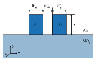
A slot waveguide based on a standard silicon-on-insulator wafer is assumed as the basic structure discussed in this paper, which is depicted in Fig. 1. Two silicon arms with a thickness of 220 nm are separated by a narrow air slot and located on the top of a 2 μm silica buried oxide layer. In our model, the refractive indices of air, silicon and silica at 1 550 nm are chosen as 1.0, 3.476 4 and 1.444[21], and the nonlinear refractive indices are 4.5×10⁻¹⁸ and 2.6×10⁻²⁰ m2·W-1[21] for silicon and silica, respectively.
The strength of the third-order nonlinear interaction in a waveguide is described by the nonlinear parameter γ, which depends on the waveguide geometry as well as the nonlinear-index coefficient n2 of the nonlinear material. In order to accurately evaluate the nonlinearity, in this paper, a full vectorial model is employed, which expresses the nonlinear coefficient of a waveguide in a generalized form as[24]
where λ is the operating wavelength, Aeff is the effective mode area, and n2 is the averaged nonlinear refractive index. The expressions of Aeff and n2[24] are
In Eq. (2) and Eq. (3), E and H are the electric and magnetic fields of the propagating mode, respectively, ez is the unit vector pointing in positive z-direction, which is also the propagation direction of the guided mode, ε0 and μ0 are respectively the permittivity and the permeability of vacuum, and n(x, y) and n2(x, y) are the linear and nonlinear refractive indices, respectively. From Eq. (3), n2 can be viewed as the nonlinear refractive index averaged over an inhomogeneous cross section weighted with respect to the field distribution.
According to Eq. (1) and Eq. (3), we need to enlarge Aeff or to degrade the power in the nonlinear material or both, so as to suppress the nonlinear interaction in the slot waveguide. It should be noted that a high power confinement in the slot region should be guaranteed so as to bring out the merit of the slot waveguide.
2 Results of nonlinearity reduction in air-cladding slot waveguides
2.1 Effects of silicon-arms width
Considering the state of the art of silicon-on-insulator circuits, the width of the slot is set as 100 nm at first while the width of the silicon arms is gradually varied from 200 nm to 400 nm with a pace of 10 nm. The power distributions in each region of the waveguide are given in Fig. 2(a). When the width of the silicon arms is decreased, the portion of power in the silicon arms decreases, and the portion of power in the substrate increases. That is, there is an obvious and quick power exchange between the silicon arms and the substrate. Meanwhile, the power confinement in the slot region changes slowly, and it holds a maximal power confinement factor of 17% when the width of the silicon arms is 250 nm. The mode profiles for WSi of 200 nm, 230 nm, 250 nm and 350 nm are shown in Fig. 2(c)~(f), respectively. We can clearly see that the silicon arms possess less power, and more power leaks to the substrate when the silicon arms are thinner, which is in accordance with the variation trend in Fig. 2(a).
Figure 2.The power distributions, effective mode area, nonlinear coefficient and mode profiles as a function of WSi
Fig. 2(b) shows that the effective mode area increases and the nonlinear coefficient decreases when the width of the silicon arms is decreased. Especially, when the width of the silicon arms is smaller than 250 nm, the effective mode area has a sharp increase owing to more power penetrates into the substrate, which can be affirmed by Fig. 2(a) and (c). Both a low power portion in the silicon arms and a large effective mode area lead to a low nonlinearity. It can be seen the minimal nonlinear coefficient (6.5 W-1·m-1) is achieved when the effective refractive index approaches 1.444, i.e., the cut-off of the mode. For efficient mode guiding, the effective refractive index should be larger than the refractive index of silica to reduce the leakage loss through the substrate. The grey regions in Fig. 2(a) and (b) denote the situation that the effective index is under 1.444. In the following discussion, the data for the slot waveguide with an effective index below 1.444 have been neglected.
2.2 Effects of slot width
Besides the width of the silicon arms, the slot width also has impact on the optical nonlinearity and the power confinement of the slot waveguide. Fig. 3 shows the effect of the slot width on the power confinement of the slot waveguide. When the slot is narrowed down, the effective index of the slot waveguide is increased. Thus the whole waveguide can confine the optical field better. Especially for the slot region, the optical field is strengthened when the slot width is decreased, which can be confirmed from the mode profiles for the slot widths of 50 nm, 100 nm and 150 nm displayed in Fig. 3(a)~(c), respectively.
Figure 3.Dependences of the mode profiles, the normalized intensity in the slot and the power confinement factor on Wslot
Fig. 3(d) shows the impact of the slot width on the normalized intensity in the slot, defined as Islot=Pslot/(Wslot×t), where Pslot is the normalized optical power in the slot (the power confinement factor), Wslot and t are respectively the width and the thickness of the slot. It can be noted that the normalized intensity in the slot increases when the slot is narrowed down. Take the slot widths of 50 nm and 100 nm for example. The maximal normalized intensity in the slot for the slot width of 50 nm is 18 μm-2, which is twice larger than 7.7 μm-2 for the slot width of 100 nm. Meanwhile the area for the slot width of 100 nm is twice the area for the slot width of 50 nm for the same thickness of the slot. So the maximal normalized power confined in the 50 nm-slot is larger than that of 100 nm-slot. The maximal normalized power confined in the slot can be improved by narrowing the slot, which is consistent with the variation trend in Fig. 3(e). When the width of the slot is decreased from 150 nm to 50 nm, the power confined in the slot keeps raising for the fixed width of the silicon arms. The maximal power confinement factor is improved from 14% (Wslot=150 nm) to 22% (Wslot=50 nm).
It can be seen from Fig. 4(a), the effective mode areas are almost the same for each width of slot when the fixed width of the silicon arms is larger than 340 nm. It is because the mode is mainly concentrated in the wide silicon arms now. However, the effective mode area decreases with the decreasing of the slot width for a fixed width of the silicon arms smaller than 340 nm. The decrease of the effective mode area results from the stronger confinement of light in the narrower slot. According to Eq. (1), a small effective mode area gives rise to a high nonlinearity. For the fixed narrow silicon arms, the nonlinear coefficient of a wide slot waveguide is lower than that of a narrow slot waveguide. We can clearly see from Fig. 4(b) that the minimal nonlinear coefficients for different slot widths are almost the same and achieved near the cut-off conditions. In addition, the corresponding nonlinear coefficients for the maximal power confinement factors for the slot waveguides with different widths of slot are all above 20 W-1·m-1.
Figure 4.Variations of the effective mode area and nonlinear coefficient with Wslot
As is well known, the quasi-TE mode, which has a discontinuity of the electric field perpendicular to the interfaces of the silicon arms and the air slot, is tightly confined in the slot. And the slot is enclosed by the two silicon arms. So we believe that thicker silicon arms will provide an extra enhancement of power constraint in the slot region.
The thickness of the silicon arms varying from 300 nm to 600 nm is considered here and the width of the slot is fixed at 100 nm. For the convenience of comparison, the situation of the waveguides with 220 nm-thick arms is also included. Fig. 5 displays the variation of the normalized intensity in the slot with the thickness. It is clearly that the maximal normalized intensities in the slot for different thicknesses are all in the range from 7.5 μm-2 to 8.5 μm-2. The mode profiles in the inset of the Fig. 5 also show the thickness has little impact on the normalized amplitude of the optical field in the slot. Although the maximal normalized intensities in the slot for different thicknesses of the silicon arms are almost the same, the maximal normalized power (Pslot=Islot×Wslot×t) still can be improved through the increase of the thickness. As is shown in Fig. 6(a), it is obvious that the power confinement factor has been greatly improved with the increase of the silicon layer thickness. The maximal power confinement factor is increased from 17% (t=220 nm) to 45% (t=600 nm).
Figure 5.Normalized intensity in the slot for different thicknesses of the silicon arms
Fig. 6 shows the effect of the thickness variation on the power confinement factor and the nonlinear coefficient. In the high power confinement region where WSi is lower than 250 nm, it is clearly that the nonlinear coefficient increases along with the thickness as fixing the widths of the slot and the silicon arms. It can also be discerned from Fig. 6(b) that the minimal nonlinear coefficients maintain the same level for the different thickness of the silicon arms. Fig. 6 certifies that the thickness of the silicon layer plays a dominant role in improving the power confinement factor while maintaining the low nonlinearity.
In conclusion, for the air-cladding slot waveguides with different structural parameters, the minimal nonlinear coefficients are almost the same (6.5 W-1·m-1) and even lower than 6.77 W-1·m-1 of the double-slot waveguide. However, the minimal nonlinearity is achieved near the cut-off condition, which increases the leakage loss through the substrate. In addition, for the air-cladding slot waveguide, the maximal power confinement factor is obtained under an optimal width of the silicon arms, and the width of the slot and the thickness of the silicon layer can be used to improve the maximal power confinement factor further. However, the corresponding nonlinear coefficients for the maximal power confinement factors for the air-cladding slot waveguides with different structural parameters are all above 20 W-1·m-1. Therefore, the low nonlinearity and high power confinement can not be obtained simultaneously for the air-cladding slot waveguide.
3 Simultaneous low nonlinearity and high confinement in slot waveguides
As analyzed and confirmed in the section 2, the width of the silicon arms, the slot width and the thickness of the silicon layer all affect the nonlinearity and the power confinement of the slot waveguide. Compared with the thickness of the silicon layer, the widths of the slot and the silicon arms are easier to be adjusted in the fabrication. In addition, the optimal width of the silicon arms can be found for each slot width to realize the maximal power confinement factor. So the slot width is primarily considered in the following discussion. The thickness used here is set as 500 nm, which is the same as in the previous work[21] for the multiple-slot waveguides. For each slot width, the width of the silicon arms is chosen accordingly to achieve the maximal power confinement factor for the slot waveguide.
According to the results in section 2.2, for the air-cladding slot waveguide, the wide slot can be employed to reduce the nonlinear coefficient, but it also decreases the maximal power confinement factor. The root cause is that the refractive index of the cladding (air) is smaller than the refractive index of the substrate (silica), thus the mode profile of the waveguide is asymmetric and tends to diffuse into the substrate. When the slot is broadened, the leakage to the substrate aggravates and leads to the decrease of the power confinement in the slot. For purpose of observing the leakage explicitly, Fig. 7(a)~(c) show the mode profiles in log scale for the air-cladding slot waveguide with the slot width of 100 nm, 160 nm and 240 nm, respectively. It is confirmed that the mode profile of the waveguide is asymmetric and tends to diffuse into the substrate. In addition, the leakage to the substrate is indeed more serious for the slot waveguide with the wider slot.
Figure 7.Mode profiles in log scale for the air-cladding and the silica-cladding slot waveguides
Based on the discussion above, it is believed that a symmetric mode profile can alleviate the power leakage to the substrate, thus the maximal power confinement factor can be maintained when the slot is broadened. The mode profiles of the silica-cladding slot waveguide with the slot width of 100 nm, 160 nm and 240 nm are given in Fig. 7(d)~(f), respectively. As expected, the mode profile is symmetric and the leakage to the substrate is alleviated. When the slot is broadened, the mode spreads out in all directions of the waveguide, so the leakage to the substrate is not particularly increased and the maximal power confinement in the slot would be maintained. Therefore, the wide slot can be employed to reduce the nonlinear coefficient without decreasing the maximal power confinement in the slot.
The effect of the slot width on the normalized intensity in the slot is provided in Fig. 8(a). The maximal normalized intensity decreases along with the increase of the slot width. Take the slot widths of 100 nm and 200 nm for example. The maximal normalized intensity in the slot for the slot width of 100 nm is 8.5 μm-2, which is twice 4.25 μm-2 for the slot width of 200 nm. When considering that the area for the slot width of 200 nm is twice the area for the slot width of 100 nm, the maximal normalized power confined in the slot is nearly unchanged for different slot widths, which can be seen from Fig. 8(b).
Figure 8.Effect of the slot width on the normalized intensity, the power confinement factor andthe nonlinear coefficient of the silica-cladding slot waveguide
Next, the effect of the slot width on the nonlinear coefficient is discussed. When the slot is broadened, the area of the silicon arms is not affected, but the normalized intensity in the silicon arms decreases as shown in Fig. 8(a). So the normalized power confined in the silicon arms decreases. Meanwhile, the broaden slot brings the increase of the effective mode area as shown in Fig. 7. The decrease of the power in the silicon arms and the increase of the effective mode area result in the decrease of the nonlinear coefficient. The nonlinear coefficient decreases with the broadening slot as shown in Fig. 8(b).
Till now, the influence of the silica cladding has been revealed. As expected, the silica-cladding slot waveguide has a symmetric mode profile and the leakage to the substrate is alleviated. It is proved that the slot width has little impact on the maximal power confinement factor and can be utilized to reduce the nonlinear coefficient. Therefore, the simultaneous low nonlinearity and high power confinement can be achieved in the silica-cladding slot waveguide.
The coloured points in Fig. 8(b) denote the corresponding nonlinear coefficient of the maximal power confinement factors for different Wslot. Through broadening the slot, we can reduce the corresponding nonlinear coefficient for the maximal power confinement factor to the levels of the nonlinear coefficients for the double-slot and triple-slot waveguides[21], which are represented with the dotted and dashed lines. For clarity, the nonlinear coefficients and the power confinement factors for different slot waveguides are displayed in Table 1. For the single-slot waveguide in this work, it can be clearly concluded from Table 1 that the nonlinear coefficient decreases with the broadening slot while the power confinement factor is maintained. Compared with the single-slot waveguide in Ref. [21], the nonlinear coefficient is lower and the power confinement factor is higher in the single-slot waveguide in this work. Furthermore, the nonlinear coefficient can be lower than those in the double- and triple-slot waveguides when the width of the slot is larger than 160 nm and 220 nm, respectively. From what has been discussed above, the simultaneous low nonlinearity and high power confinement in the slot waveguide in this work is comparable with those in Ref. [21]. In addition to this, the single 240 nm-wide slot is easy to be fabricated in contrast with the equally distributed 50 nm-wide slots for the multiple-slot waveguides. Besides, the single-slot waveguide in this work has a large tolerance to the fabrication error. For the width of the slot from 100 nm to 240 nm, we can always achieve simultaneous low nonlinearity and high power confinement. Lastly, the silica-cladding would reduce the scattering loss by smoothing the sidewall roughness[25, 26] while the multiple slots would bring about large scattering loss on account of additional sidewalls.
Structure
Parameters
Performances
Ref.
Cladding
Wslot/nm
t/nm
γ/(W-1·m-1)
Γ
* These data are calculated based on the information derived from Ref. [21]. And the missing value for the triple-slot waveguide is due to the lack of structural parameters.
Single-slot waveguide
Silica
100
500
11.28
43%
In this work
120
9.21
43%
140
7.73
43%
160
6.63
43%
180
5.78
43%
200
5.10
43%
220
4.57
42%
240
4.12
42%
Single-slot waveguide
Air
100
500
16.11
40%*
[21]
Double-slot waveguide
50/50
6.77
48%*
[21]
Triple-slot waveguide
50/50/50
4.66
—
[21]
Table 1. Performances of the nonlinearity and the power confinement for different slot waveguides
As a whole, the single-slot waveguide can achieve simultaneous low nonlinearity and high power confinement which are even comparable with those of the multiple-slot waveguides. We have studied the effects of the geometry and the cladding condition on the nonlinearity and the power confinement of the single-slot waveguide. For the air-cladding slot waveguide with different structural parameters, the minimal nonlinear coefficient is achieved near the cut-off condition and almost the same. The maximal power confinement factor can be improved by narrowing the slot or thickening the silicon layer. However, the low nonlinearity and high power confinement can not be obtained simultaneously for the air-cladding slot waveguide. By covering the single-slot waveguide with silica, a symmetric mode profile is achieved and the power leakage to the substrate is alleviated, thus the wide slot can be utilized to reduce the nonlinear coefficient without decreasing the maximal power confinement factor. Simultaneous low nonlinearity and high power confinement is achieved in the silica-cladding slot waveguide.
The performed study in this paper shows that tailoring the geometry and the cladding condition allows optimizing and realizing a slot waveguide with both low nonlinearity and strong power constraint at the same time. Especially, the nonlinear coefficient can be lower than the reported values of multiple-slot waveguides, and the fabrication difficulty and extra sidewall scattering loss of the multiple-slot waveguides can be avoided as well. Instead of introducing additional slots into the single-slot waveguide, work in this paper provides another effective way to reduce the nonlinear coefficient and improve the power confinement factor in slot waveguides simultaneously, which would provide guidance for the design of linear integrated optical circuits and devices utilizing slot waveguides. The slot waveguide with both low nonlinearity and strong power confinement would be beneficial to many applications, such as optical sensing and filtering.
Shu-bo HU, Ya-meng XU, Jia-xuan LI, Mei KONG. Simultaneous Low Nonlinearity and High Power Confinement in Slot Waveguides[J]. Acta Photonica Sinica, 2020, 49(2): 0213002