• Journal of Atmospheric and Environmental Optics
  • Vol. 18, Issue 2, 89 (2023)
SU Yuan1, WU Linlin2、*, TAO Fa3, HU Shuzhen3, and CHENG Xin1
Author Affiliations
  • 1Hefei Meteorological Bureau National Basic Weather Station, Hefei 230041, China
  • 2Weather Modification Office of Anhui Province, Hefei 230031, China
  • 3Meteorological Observation Center, China Meteorological Administration, Beijing 100081, China
  • show less
    DOI: 10.3969/j.issn.1673-6141.2023.02.001 Cite this Article
    Yuan SU, Linlin WU, Fa TAO, Shuzhen HU, Xin CHENG. Joint inversion of cloud height by visible/infrared full sky imager and cloud radar[J]. Journal of Atmospheric and Environmental Optics, 2023, 18(2): 89 Copy Citation Text show less
    Visible/infrared full sky imager. (a) Visible light imager; (b) infrared full sky imager
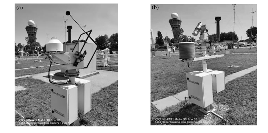
    Fig. 1. Visible/infrared full sky imager. (a) Visible light imager; (b) infrared full sky imager
    YLU1 Ka-band millimeter-wave cloud radar
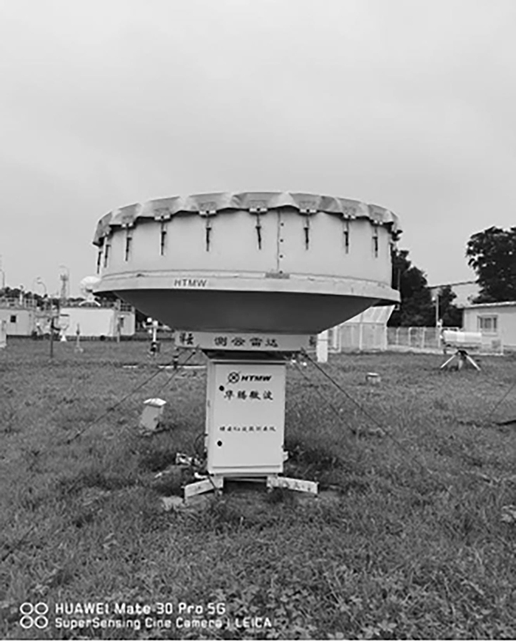
    Fig. 2. YLU1 Ka-band millimeter-wave cloud radar
    Comparison of gray values with and without clouds at the same time
    Fig. 3. Comparison of gray values with and without clouds at the same time
    Scatter diagram of cloud height and gray value before quality control in June, 2019
    Fig. 4. Scatter diagram of cloud height and gray value before quality control in June, 2019
    Scatter diagram of low cloud height and gray value below 2500 m
    Fig. 5. Scatter diagram of low cloud height and gray value below 2500 m
    Scatter diagram and correlations of medium cloud height and gray value below 6000 m
    Fig. 6. Scatter diagram and correlations of medium cloud height and gray value below 6000 m
    Scatter plots of medium and high cloud height and gray value above 6000 m
    Fig. 7. Scatter plots of medium and high cloud height and gray value above 6000 m
    Scatter diagram of cloud height and gray value after quality control in June, 2019
    Fig. 8. Scatter diagram of cloud height and gray value after quality control in June, 2019
    Comparison of actual and inversion cloud heights in zenith direction
    Fig. 9. Comparison of actual and inversion cloud heights in zenith direction
    The area within the zenith angle of about 30° near the zenith at 07:30 on June 4, 2019
    Fig. 10. The area within the zenith angle of about 30° near the zenith at 07:30 on June 4, 2019
    Three-dimensional distribution of gray value within 30°zenith angle of infrared cloud image at different cloud heights
    Fig. 11. Three-dimensional distribution of gray value within 30°zenith angle of infrared cloud image at different cloud heights
    Relationship between downward infrared radiation and zenith angle cosine in clear sky
    Fig. 12. Relationship between downward infrared radiation and zenith angle cosine in clear sky
    Comparison between the cloud height obtained by linear inversion of the relationship between infrared radiation and zenith angle cosine and the cloud height obtained taking the zenith angle of about 30° near zenith
    Fig. 13. Comparison between the cloud height obtained by linear inversion of the relationship between infrared radiation and zenith angle cosine and the cloud height obtained taking the zenith angle of about 30° near zenith
    Table 1. Performance indicators of millimeter-wave cloud radar
    EquipmentDetection elements
    Millimeter wave cloud radarReflectivity profile, cloud bottom, cloud top, cloud thickness
    Dual band sky imagerCloud amount, infrared brightness temperature diagram
    Table 2. Main parameters obtained by each device of the system
    Yuan SU, Linlin WU, Fa TAO, Shuzhen HU, Xin CHENG. Joint inversion of cloud height by visible/infrared full sky imager and cloud radar[J]. Journal of Atmospheric and Environmental Optics, 2023, 18(2): 89
    Download Citation