Yi Dong, Zhangweiyi Liu, Xiaocheng Wang, Nan Deng, Weilin Xie, Weisheng Hu. Distribution of millimeter waves over a fiber link with high frequency stability (Invited Paper)[J]. Chinese Optics Letters, 2016, 14(12): 120006
Copy Citation Text
We present a theoretical analysis, systematic simulation, and experimental measurements for the phase noise, timing jitter, and frequency stability in the frequency distribution of millimeter waves over distant optical fiber links. The conception that the dissemination of a higher frequency reference instead of a lower one can achieve a better frequency stability is discussed and verified. We find that the system’s noise floor, including thermal noise, shot noise, and any other noise from electronic components, is considered to be a fundamental limitation for a frequency reference transmission system. Benefiting from the high-precision time delay variation discrimination and accurate locking control operation, a highly stabilized reference is distributed to a remote end over a 60 km spooled fiber, achieving a frequency stability of at an average time 1000 s, corresponding to 23 fs of RMS timing jitter (0.01 Hz–1 MHz).
Long-distance distribution of highly stabilized frequency references has been shown to play an important role in radio astronomy[1,2], such as the Atacama Large Millimeter Array project[3,4] and very long baseline interferometry[5,6]. Applications that involve high-precision phase synchronization among antennas usually demand a well-synchronized high-frequency reference with low timing jitter. Over the past decades, optical fibers have become an increasingly attractive medium for the remote distribution of local stable signals, due to their low attenuation, wide bandwidth, high reliability, and immunity to electromagnetic interference[7]. However, mechanical stress and temperature variations on the fiber links may cause transmission delay variations. This will degrade the phase stability of the distributed reference at the remote end.
To solve this problem, various frequency distribution schemes[8–14] based on round-trip phase correction have been reported. The compensation rests on the measurement of the phase of the signal after one round trip to apply a correction to the transmitted signal. Compared with the optical delay compensation[8–10], electronic phase correction[11–14], such as voltage-controlled oscillator (VCO) -based schemes, has an infinite compensation range, faster frequency response, and higher environmental tolerance. However, it is hard to achieve a high-frequency reference distribution due to the bandwidth restrictions of microwave devices and the high voltage sensitivity of VCOs.
In practice, a high transmission carrier frequency enables highly precise time delay variation detection to improve the signal-to-noise ratio that is deteriorated by thermal noise, shot noise as well as any other noise[15]. This means that dissemination of a higher frequency reference can achieve a better frequency stability. In order to realize phase discrimination and fast phase correction at high frequencies, we proposed the dual-heterodyning phase error transfer (DHPT) and acousto-optic frequency shifter (AOFS) -based phase corrections scheme in our previous work[16].
Sign up for Chinese Optics Letters TOC. Get the latest issue of Chinese Optics Letters delivered right to you!Sign up now
In this Letter, we first propose a millimeter-wave dissemination system via spooled fiber links. Focusing on the system, an analytical model based on the phase-locked loop (PLL) theory is built and adopted to investigate the influences of the limiting factors for distant distributions of high-frequency references through turbulent fiber links. Next, we study the relationship between the frequencies of the transmitted reference and the system stability. The distributions of 50, 100, 200, and 400 GHz millimeter-wave signals over a 60 km spooled fiber are experimentally demonstrated. The system’s phase noise floor, including the thermal noise, shot noise, and other noise from electronic devices, is precisely measured in the condition of phase-locked 1 m fiber link. We find that these noises are considered to be a fundamental limitation in frequency transmission systems. The idea of disseminating a high-frequency reference instead of a lower one to achieve a better frequency stability is confirmed. Finally, we demonstrate a stable distribution of 400 GHz local signal over 10, 20, and 40 km spooled fibers. The long-term stability achieves a level of at 1000 s averaging time, corresponding to RMS timing jitter of tens of femtoseconds.
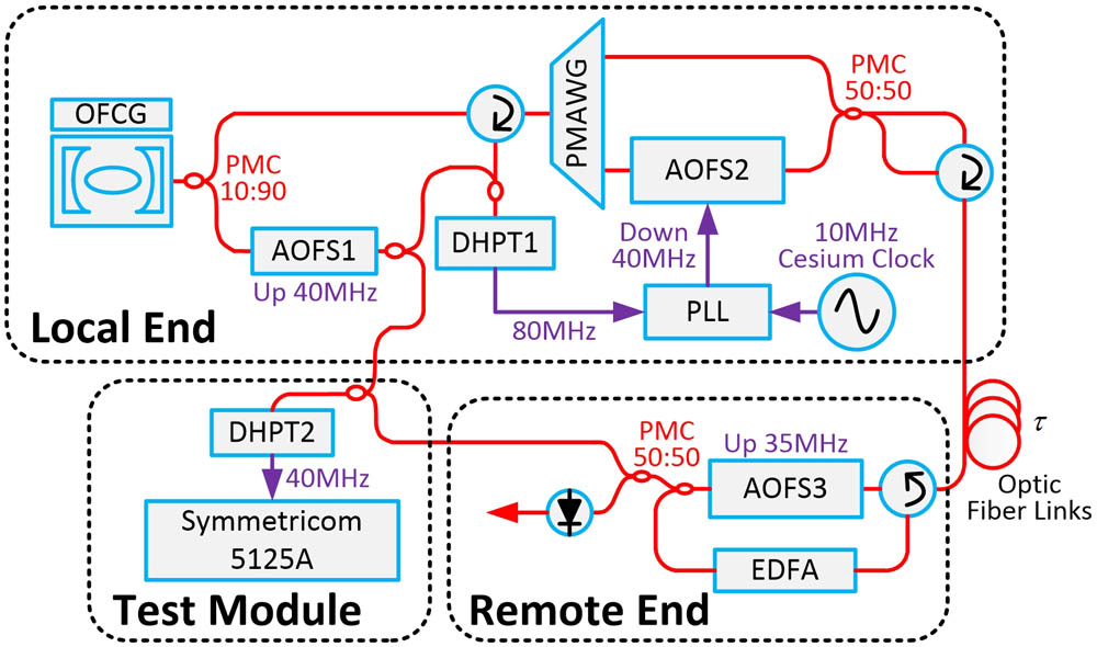
The experimental setup is illustrated in Fig. 1. At the local end, an optical frequency comb with a 25 GHz repetition frequency is divided into two branches: one is used to generate and transmit the millimeter-wave signal, and the other is upshifted 40 MHz as a reference for detecting the phase noise from the fiber link. A polarization-maintaining arrayed waveguide grating is adopted to select two spectral lines. The obtained millimeter waves can have spacings of 50, 100, 200, and 400 GHz. The DHPT1 and AOFS2 are used to obtain and compensate for the phase noise induced from the optic fiber links. At the remote end, the signal is upshifted 35 MHz by AOFS3 to distinguish the round-trip signal from backscattered signals. It is also amplified by an erbium-doped fiber amplifier (EDFA) to compensate for the optical loss. In a closed-loop operation, a phase-stable millimeter-wave signal is obtained at the remote end.
Figure 1.Simplified schematic setup of millimeter-wave signal distribution system. OFCG, optical frequency comb generator; PMAWG, polarization-maintaining arrayed waveguide grating; PMC, polarization-maintaining coupler; DHPT, dual heterodyne phase error transfer.
Based on this distribution system, a basic PLL model is built, and the transfer functions of the whole system are obtained. By using the Laplace notation, the open loop gain can be expressed as where , , and are the gain of the phase detector, loop filter, and VCO, respectively. is the ratio of the frequency divider. is the one-way fiber propagation delay. It is well known that the system’s bandwidth is limited by the transmission delay in a feedback loop system[17]. Therefore, the noise suppression can achieve the optimum performance through the appropriate design. Here, we assume that the frequency reference signal suffers the same phase drift over the fiber links in both directions. At the local end, an 80 MHz intermedia frequency is obtained in DHPT1, whose phase represents the phase fluctuations of the round-trip millimeter-wave signal. The phase noise power spectrum density (PSD) of 80 MHz signal can be expressed as where we let convert to frequency space, and where and are the single sideband phase noise PSDs of the generated millimeter-wave signal and the one-way propagation fiber noise. and are the angular frequencies of the millimeter-wave signal and the 25 GHz microwave signal. On one hand, the phase noise of the millimeter wave ideally multiplies from the 25 GHz microwave. It should be low enough to avoid excess noise. On the other hand, the phase noise induced from fiber links is proportional to the frequency square of the transferred signal[18]. When the PLL is active, the phase noise induced from the fiber links is discriminated and compensated; thus, a stabilized millimeter-wave signal can be obtained at the remote end.
To evaluate the performance of the distribution system, the residual phase noise PSD of a distributed millimeter wave is obtained by measuring the phase noise of the 40 MHz heterodyne beat note between local and remote signal. The 40 MHz frequency is obtained in DHPT2, shown in Fig. 1. By using the usual algebra[19], the phase noise PSD of a millimeter-wave signal with one-way propagation at the remote end can be expressed as where the system’s phase noise consists of thermal noise, shot noise, and other noise from electronic components, such as PLL circuits, amplifiers, and photodetectors.
Besides the phase noise spectra, both the frequency stability and RMS timing jitter of the transmission system can be calculated directly from the phase noise PSD by using a weighting function. The Allan deviation and RMS timing jitter can be expressed as where is the averaging time. and are integration ranges from the phase noise spectra.
In a closed-loop operation for the distribution of 50–400 GHz signals over a 60 km spooled fiber, the simulation and measurement results are shown in Fig. 2, including the residual phase noise, Allan deviation, and RMS timing jitter. Firstly, the system noise floor is simulated and measured in the condition of 1 m fiber links. A bump can be observed around 200 Hz, which is the bandwidth of the control loop. Next, the residual phase noise is shown in both Figs. 2(a) and 2(b). In the simulation, with the increase of the frequency of the transferred signal, the residual phase noise shows a proportionate increase () at the high Fourier frequency regime, as seen in Fig. 2(a). Below 1 Hz, the noise suppression is nearly limited by the system’s noise floor. The trend also can be observed in the experimental measurement results, as shown in Fig. 2(b). Then, the Allan deviations of the simulation and measurement results are plotted in Figs. 2(c) and 2(d). It is shown that the experimental results of the long-term frequency stability get better from to at 1000 s when a higher frequency reference is transferred, which verifies the theoretical analysis. Finally, the RMS timing jitter of the simulation and measurement results as well as the theoretical limit are shown in Fig. 2(e), which are all calculated by integrating the phase noise PSD from 0.01 Hz to 1 MHz. As the frequency increases from 50 to 400 GHz, the simulation and measurement RMS timing jitters decrease from 76 to 22 fs and from 68 to 24 fs, respectively. These two curves are both approaching the theoretical limit that is calculated when the system noise floor is ignored. Benefiting from the highly precise time delay variation discrimination and correction, the impact of the intrinsic system’s noise can be minimized. Thus, the long-term frequency stability can be enhanced to reach the theoretical limit. Consequently, the idea of thoroughly disseminating a higher frequency reference to achieve better system stability is verified.
Figure 2.Results for distribution of 50, 100, 200, and 400 GHz millimeter-wave signals over a 60 km spooled fiber. (a) The simulated residual phase noise. (b) The measured residual phase noise. (c) The simulated Allan deviation. (d) The measured Allan deviation. (e) The simulated RMS timing jitter (red circle), the measured RMS timing jitter (bule triangle) and theoretical limit RMS timing jitter (black square).
In a closed-loop operation for the distribution of a 400 GHz reference signal over 10, 20, and 40 km spooled fibers, the simulation and measurement results are shown in Fig. 3. Figures 3(a) and 3(b) illustrate the residual phase noise of the 400 GHz reference signal. Bumps of the loop bandwidth can be observed around 300, 600, and 1200 Hz corresponding to the 40, 20, and 10 km fiber links, respectively. At the low Fourier frequency below 1 Hz in Fig. 3(a), the fiber links’ induced phase noise is well suppressed and limited by the fundamental system noise floor; the same trend can also be observed in Fig. 3(b). The results of the Allan deviations are plotted in Figs. 3(c) and 3(d). The short-term frequency stability is deteriorating as the transmission distance increases, while the long-term frequency stability approaches the fundamental limitation of the transmission system at the level of . The RMS timing jitter is plotted in Fig. 3(e). The simulation and measurement timing jitter of the 10, 20, and 40 km fibers increase from 14.5 to 19.2 fs and from 14.2 to 15.8 fs. It can be noticed that the longer the transmission distance is, the larger the timing jitter will be. This can mainly be attributed to the non-suppressed out-of-loop phase noise.
Figure 3.Results for distribution of 400 GHz reference signal over 10, 20, and 40 km spooled fibers. (a) The simulated residual phase noise. (b) The measured residual phase noise. (c) The simulated Allan deviation. (d) The measured Allan deviation. (e) The simulated RMS timing jitter (black square) and the measured RMS timing jitter (red circle).
In conclusion, a remote distribution system model based on the PLL theory is built. We present a theoretical analysis, which is also verified through experimental results. By transmitting 50 to 400 GHz reference signals to the remote end over a 60 km spooled fiber, we show that the system noise, including shot noise, thermal noise, and any other noise from electronics components, is considered to be a fundamental limitation for a frequency reference transmission system. It is confirmed that instead of disseminating a lower frequency reference, a higher one can lead to better frequency stability owing to the highly precise time delay variation discrimination and accurate locking control operation. A highly stabilized reference is distributed to the remote end. The proposed system exhibits tens of femtoseconds’ frequency synchronization precision. Moreover, the long-term frequency stability can be achieved at the level of over a transmission range as large as 60 km.
Yi Dong, Zhangweiyi Liu, Xiaocheng Wang, Nan Deng, Weilin Xie, Weisheng Hu. Distribution of millimeter waves over a fiber link with high frequency stability (Invited Paper)[J]. Chinese Optics Letters, 2016, 14(12): 120006