Guangdong Provincial Key Laboratory of Optical Fiber Sensing and Communications, Institute of Photonics Technology, Jinan University, Guangzhou 510632, China
We report on temperature compensation for beat-frequency-encoded dual-polarization fiber laser sensors based on a cleave-rotate-splice method. By cleaving the laser cavity into two segments with comparable lengths, aligning them with a rotated angle of 90°, and then fusion splicing the two halves, the temperature sensitivity in terms of beat-frequency variation can be greatly reduced from to (or by 84.9%). In contrast, the sensitivity to point loaded mass hardly changes. We also find that the beat-frequency fluctuation decreases from to as a result of the temperature compensation.
A fiber Bragg grating (FBG) sensor is one of the most important category of fiber optics sensors, taking advantage of the in-fiber structure, compact size, and intrinsic multiplexing capability. In recent years, they have found diverse applications including health monitoring of large-scale infrastructures, down-hole exploration, and aerospace industries[1]. Temperature cross sensitivity has always been a disadvantageous factor that affects the measurement accuracy for practical applications[2,3]. An FBG typically presents a thermal response of in terms of Bragg-wavelength shift, due to the thermal expansion and thermo-optic effect of silica glass. In contrast, the strain sensitivity is about , which yields a temperature cross sensitivity of . In order to overcome this problem, a straightforward approach is to employ a reference sensor. Two independent Bragg gratings are subjected to strain and strain-free for temperature monitoring, respectively. As a result, extremely high () resolutions can be achieved[4,5]. Alternatively, approaches based on resolving a coefficient matrix have been demonstrated. This strategy involves employing sensing elements including FBGs in combination with other types of photonic devices to obtain different optical responses to different measurands[6–13]. Alternatively, a single FBG sensor with a specially designed package or a superstructured grating can be used[14–18]. However, it is more favorable to fabricate a temperature-compensated sensor to measure the mechanical parameters independently, to reduce the sensor amount and minimal package size for practical applications.
The dual-polarization fiber laser sensor is a derivation of conventional passive FBG sensors. They are fabricated by inscribing a wavelength-matched FBG pair (or a single phase-shifted grating) into a rare-earth-doped fiber. Pumped with a laser diode at the absorption band, the cavity naturally generates two orthogonal polarization modes with a certain frequency difference. The radio-frequency beat signal between these two modes can be used for sensing, taking advantage of its extremely narrow linewidth, high signal-to-noise ratio, and intrinsic sensitivity to perturbations that can induce a nonuniform stress. For example, this sensor has exhibited a sensitivity of to a transverse load, as a result of the induced change in intracavity birefringence. These beat-frequency-encoded fiber laser sensors also suffer from temperature cross sensitivity in a different way from their wavelength-encoded counterparts. The beat signal can exhibit thermal sensitivities varying from several to hundreds of kHz/°C, depending on its transverse geometry and the amplitude of thermal stresses[19]. In this work, we demonstrate temperature compensation for the frequency-encoded fiber laser sensors. The fiber laser is cleaved into two sections, aligned with a rotated angle of 90°, and then fusion spliced together as a laser cavity. The thermal sensitivity is reduced from to , (or by 84.9%) as a result of the compensation in the thermally induced change in optical path between the two orthogonal polarizations. By taking this treatment, one can effectively reduce the effect of thermal cross sensitivity without the use of a reference sensor.
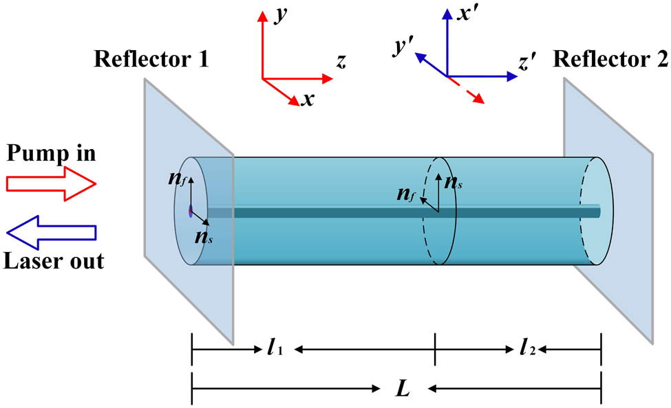
Figure 1 schematically shows the principle of the temperature compensation. The laser comprises two mirror reflectors for optical feedbacks in a gain fiber. The laser can operate in single longitudinal mode at each orthogonal polarization axis with a cavity length of mm order. Due to the imperfection in the circular symmetry of the fiber core, a weak intrinsic birefringence exists in the fiber. Assume that the and polarization modes correspond to the slow and fast axis, respectively. Both polarization modes should satisfy the resonant condition where denotes the speed of light in a vacuum, is the lasing frequency of each polarization mode, are the effective indices along the slow/fast axis of the optical fiber, and represents the resonant order. Equation (1) suggests that the difference in lasing frequency between the two polarization modes arises from the difference in optical path . As a result, a beat signal with frequency can be generated by the fiber laser. Derived from Eq. (1), the beat frequency can be expressed by where denotes the laser wavelength, represents the average effective index, and is the fiber intrinsic birefringence. The dual-polarization fiber laser has been exploited as photonic sensor that relies on its response in terms of the beat-frequency variation to perturbations. The sensor implementation typically involves a transduction of perturbations into a transverse load onto the laser cavity to induce a birefringence change. Taking a differentiation form of Eq. (2), its thermal response in terms of beat-frequency change can be depicted by where and are the thermal-expansion and thermo-optic coefficients of silica glass. Substituting , these two coefficients contribute out of the thermal sensitivity. The term denotes the normalized birefringence change induced by temperature variation. In Eq. (3) the phase-matching condition for the FBG is included, where Λ represents the grating pitch. Our previous work[19] suggests that the thermally induced birefringence change makes the main contribution to the thermal response, which arises from the step-index change and the relaxation of thermal stress. The change rate highly depends on its core geometry and initial thermal stress. In other words, temperature can change the effective index as well as the optical path of each polarization mode, but with different rates, which yields a shift in beat frequency.
Sign up for Chinese Optics Letters TOC. Get the latest issue of Chinese Optics Letters delivered right to you!Sign up now
Figure 1.Schematic of a temperature-compensated fiber grating laser.
In order to implement a temperature-compensated laser sensor, we cleave the laser into two sections with lengths of and , respectively, rotate one of them by 90°, and then splice them by arc discharge by use of a commercial fusion splicer. This treatment is performed to align the fast (slow) axis of the right half in accordance with the slow (fast) axis of the left one, so that the difference in optical path between the and axis is now expressed by , which indicates that the beat frequency changes to
The corresponding thermal sensitivity, modified from Eq. (3), is expressed by Equations (4) and (5) indicate that after the cleave-rotate-splice treatment the laser presents a lower beat frequency as well as a lower thermal sensitivity, depending on the contrast between the lengths of the two halves.
Figure 2 shows the experimental setup of temperature compensation for laser sensor. The laser is fabricated by photoinscribing two highly reflective, wavelength-matched Bragg gratings in an Er/Yb codoped fiber (EY305, CoreActive) by use of a 193 nm ArF excimer laser and a phase mask with a pitch of 1058.88 nm. The single-pulse energy and repetition rate are 3 mJ and 200 Hz, respectively. The reflectivities and lengths of the gratings are over 28 dB and 7.5 mm, respectively. The grating separation is 7 mm, which can yield a single-longitudinal-mode output. When pumped with a 980 nm laser diode via a 980/1550 nm wavelength division multiplexer (WDM), the fiber grating cavity emits two orthogonal polarization modes. These two modes beat at the photodetector and the beat signal is measured by an electric spectrum analyzer. An optical isolator is used to prevent unwanted optical feedback in terms of end-face reflection or scatterings. A polarization controller is used to adjust the polarization states to maximize the intensity of the beat signal.
Figure 2.Experimental setup of temperature compensation by performing a cleave-rotate-splice process. ISO: isolator. PD: photodetector. PC: polarization controller.
We cleave the laser into two segments with different lengths, rotating one of them by 90° and then splicing them with a fusion splicer. Figure 3 shows the typical frequency spectrum of a fiber laser before and after this treatment, respectively. The original beat frequency is 2.466 GHz, which indicates that the intracavity birefringence is about . Its output beat frequency changes to 510.7 MHz after the cleave-rotate-splicing process, which is a result of the partial compensation in optical path between the two orthogonal polarization directions.
Figure 3.Measured beat spectra of the fiber grating laser before and after the cleave-rotation-splice treatment.
We carried out the treatment for lasers with different -over- ratios and then measured their thermal responses, respectively. Figure 4 shows measured beat-frequency variations as a function of environmental temperature. Different beat frequencies are obtained by cleaving the different positions of the effective cavity length of the optical fiber laser sensors. The beat frequencies are 1891, 1220, 870, and 260 MHz, respectively, for the individual samples denoted as 1 to 4. Sample 1 is an uncompensated laser. Its output frequency is different from the one in Fig. 3 due to the UV-induced birefringence change during the grating formation, which is difficult to control. The corresponding sensitivities are , , , and , which are almost in proportion to the beat frequency, in accordance with our prediction. The deviation from a linear proportionality is a result of the contribution from the thermal expansion and thermo-optic effect, which maintain invariance after the treatment, as well as the imperfection in the control of the rotation angle. Sample 4 presents a thermal sensitivity of , which is 84.9% lower than the uncompensated one, suggesting the feasibility of the proposed method. In contrast, the wavelength sensitivities to temperature change for the four samples are 9.0, 9.9, 8.8, and 12.1 pm/°C, respectively, which indicates that the thermal response in terms of wavelength shift cannot be weakened by means of this treatment. Further reduction of thermal sensitivity is limited by the following factors. First, the initial beat frequencies of fiber lasers are different with each other even though they are fabricated in the same fiber because the UV exposure during grating formation can induce a nonuniform index modulation and change fiber birefringence. The induced birefringence change is determined by the exposure dosage as well as the incident direction with respect to the fiber principle axis. Second, the local birefringence change induced by arc discharge during the fusion splicing is difficult to control. Third, the accuracy in the length contact and rotation angle is limited by the current facility.
Figure 4.Measured temperature responses of the individual temperature-compensated fiber grating lasers.
The dual-polarization-mode fiber lasers can be exploited as beat-frequency-encoded sensors for diverse mechanical parameters, e.g., acceleration, acoustic waves, and hydrostatic pressure, via proper transduction of these parameters to a transverse load on the laser cavity. Therefore, the detection capability of such a laser sensor is typically characterized by mass sensitivity. The mass sensitivity is proportional to the product , where denotes the induced local birefringence change and is the local intracavity light intensity. The birefringence change is largely related to the loading orientation. Simply speaking, the beat frequency increases and decreases with the same rate when the loading is applied along the slow and fast axis. Note that this sensitivity is weighted by the local intracavity light intensity and thereby longitudinally varies in accordance with the laser mode profile. The mass sensitivity profile is measured by scanning the loading position along the laser cavity via point contact. This is done by placing a glass rod with a mass onto the laser cavity to cause a local birefringence change and make it roll along the fiber length by use of the setup described in Ref. [20]. A dummy fiber is placed parallel to the fiber laser for balance and the measured sensitivity is half of the actual sensitivity. For convenience, the sensitivity characterization is carried out on an inclined plane with an angle .
The rod scans along the fiber laser with a speed of 0.2 mm/s and the beat frequency is measured with a step of 1 mm. The mass sensitivity of an uncompensated laser is plotted in Fig. 5(a) in blue curve. The mass is loaded along the slow axis of the cavity. The flat top corresponds to the blank region between the gratings. The mass sensitivity over this region is about 16 MHz/g. The two rapidly decreasing regions correspond to the two gratings over which the distributed reflection occurs. The measured mass sensitivity of a cleave-rotate-splice treated fiber laser is superimposed in Fig. 5(a) in the red curve. It presents a sudden conversion from negative to positive sensitivity as a result of the exchange of the fast and slow axis at the right half of the cavity. However, the amplitude of the mass sensitivity hardly changes. Figure 5(b) shows the beat-frequency changes versus applied mass for lasers before and after the treatment at the position . The measured mass sensitivities are 16.1 and 17.5 MHz/g, respectively. The deviation in mass sensitivity is attributed as the uncertainty in loading direction with respect to the fiber principle axis.
Figure 5.(a) Measured spatial sensitivity to transverse load before and after the treatment. (b) The measured responses to the applied mass for lasers before and after treatment.
Figure 6 shows the measured beat frequency fluctuation of the fiber laser before and after the treatment over 800 s. We found that the frequency fluctuation before the treatment is about while the temperature compensated one presents a fluctuation of about . The frequency fluctuation is a result of low-frequency noise, where the thermal variation makes a considerable contribution. The result suggests that the temperature compensation can partially lower the frequency fluctuation, which is beneficial for the static or quasi-static measurement of a transverse load and related measurands.
Figure 6.Measured beat frequency variation for a laser before and after temperature compensation over 800 s.
In conclusion, we demonstrate an effective method of temperature self-compensation for dual-polarization fiber grating sensors. By cleaving the laser cavity into two segments, rotating one of them by 90°, and then splicing them to reform a laser cavity one can greatly reduce the temperature sensitivity from to , or by 84.9%. The reduction in thermal response is a result of the compensated change in the thermally induced optical path between the two orthogonal polarization directions. The maximum sensitivity to the transverse load of the compensated temperature hardly changes compared with the uncompensated ones. The frequency fluctuation is partially suppressed due to the weakened thermal response, which is beneficial for static and quasi-static sensing. The thermal sensitivity can be further reduced by precisely controlling the length contrast between the two segments.