
Qian Yang, Yangfeifei Yang, Hao Li, Haigang Liu, Xianfeng Chen, "Nonlinear generation of vector beams by using a compact nonlinear fork grating," Photonics Res. 12, 1036 (2024)
- Photonics Research
- Vol. 12, Issue 5, 1036 (2024)

Fig. 1. Schematic of the experimental setup. GT prism, Glan–Taylor prism; HWP 1 HWP 2 HWP 3 QWP 1 QWP 2 QWP 3 M 1 M 2 M 3
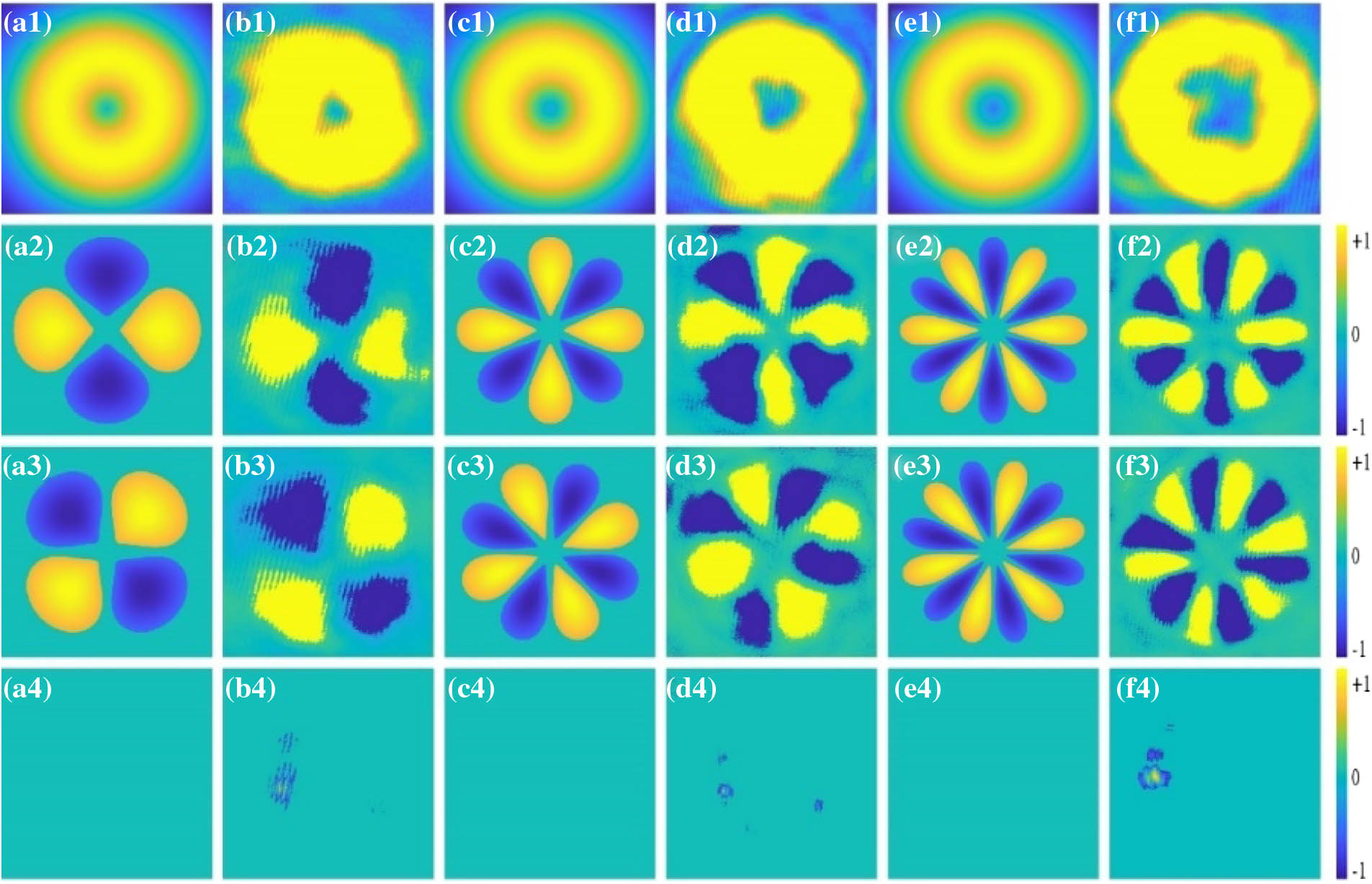
Fig. 2. Stokes parameters of SH vectorial light field. (a1)–(a4), (c1)–(c4), and (e1)–(e4), respectively, represent the simulated Stokes parameters S 0 S 1 S 2 S 3 ℓ = 1
Fig. 3. First, third, fifth rows and second, fourth, sixth rows, respectively, show the results of the SH vector beams with the topological charge ℓ = 1 2 α + Δ 1 2 − π 2 = π 3 2 α + Δ 1 2 − π 2 = π 2
Fig. 4. Experimental results corresponding to the cases of Fig. 3 . The arrows indicate the polarization direction of the polarizer.
Fig. 5. Variation of generated SH vector beams power (P 2 P 1 ℓ = 1 ℓ = 2 ℓ = 3


Set citation alerts for the article
Please enter your email address

© Copyright 2018-2021 | Chinese Laser Press. All Rights Reserved 沪ICP备15018463号-20