 AI Video Guide
  AI Picture Guide
 AI One Sentence

J. Peñas, A. Bembibre, D. Cortina-Gil, L. Martín, A. Reija, C. Ruiz, M. Seimetz, A. Alejo, J. Benlliure, "A multi-shot target wheel assembly for high-repetition-rate, laser-driven proton acceleration," High Power Laser Sci. Eng. 12, 02000e22 (2024)
- High Power Laser Science and Engineering
- Vol. 12, Issue 2, 02000e22 (2024)
Note: This section is automatically generated by AI . The website and platform operators shall not be liable for any commercial or legal consequences arising from your use of AI generated content on this website. Please be aware of this.
Abstract
Keywords
1. Introduction
The acceleration of ions from the interaction of a high-power laser with a plasma has attracted growing interest over the last two decades[1,2]. Efficient acceleration of light ions can be achieved through a variety of established and emerging accelerating mechanisms, whose dominance depends on the laser and target characteristics. Arguably, the so-called target normal sheath acceleration (TNSA) mechanism is the most-established and robust route to accelerate light ions to multi-MeV energies[3,4]. In TNSA, the laser interacts with an overdense plasma, typically generated by the pedestal preceding the main pulse in high-power systems. During the interaction, a large number of fast electrons from the front surface are driven into the target. These fast electrons will reach the target rear surface, where a fraction will leave the target and generate a quasi-electrostatic, capacitor-like field at the rear surface, with values of the order of TV m
Parallel to the studies of laser-driven ion acceleration, there has been significant progress in laser technology, not only towards achieving increasingly larger powers, but also towards the development of multi-TW laser systems with increasingly higher repetition rates. The advent of these multi-hertz high-power laser systems is leading to a growing need for novel target systems capable of operating at such rates. Due to the destruction of the target following the interaction with the laser, an appropriate system needs to be capable of replenishing the target and positioning it on the focal plane of the laser with micrometre-level precision, as given by the Rayleigh length for the short
Several alternatives are being actively studied as potential target systems[5]. Some promising recent developments include the use of liquid targets[6], liquid crystal targets[7,8], high-density gas jets[9,10] and cryogenic solid hydrogen targets[11,12], all of which would ensure the operation for extended periods of time. However, these solutions still face major challenges, such as the shape and profile manipulation, micrometric positioning and restrictions in operation due to the high-vacuum level required by the laser systems. For these reasons, target systems based on the replenishment of foil-based solid targets remain as the most common solution, typically in the form of tape-drive systems or multi-target holder systems.
Sign up for High Power Laser Science and Engineering TOC. Get the latest issue of High Power Laser Science and Engineering delivered right to you!Sign up now
Tape-drive-based targets allow for tens of thousands of shots, which at 10 Hz would correspond to almost 1 h of continuous operation[13–16]. The main drawback of these systems is the limited variety of tape materials and thicknesses suitable to withstand the mechanical stress caused by the continuous movement. In this context, multi-target holder systems appear as an appealing alternative, thanks to the flexibility of using a rigid structure to support the target foils, allowing for a broad variety of suitable target materials and thicknesses[17]. However, these configurations present two major limitations, namely the relatively reduced number of shooting positions, typically hosting fewer than 1000 targets; and the reduced repetition rate at which they can be operated, due to the need to replace and realign with micrometre-level precision after each irradiation. Recent developments have tried to tackle these limitations in order to extend the usability of multi-target holder systems.
In order to increase the number of targets, Gao et al.[17] proposed a system based on a metallic target wheel hosting target plates accommodating up to approximately
Here we report on a multi-shot target assembly based on a rotating wheel capable of hosting more than 5000 targets, which is compatible with operation at a repetition rate of 10 Hz. Furthermore, we describe the procedure implemented to ensure automatic shot-to-shot replenishment and realignment of each target at 10 Hz, based on a few-minute measurement for the pre-characterization of the shooting positions with a high-precision industrial sensor, which allows for the positioning of the targets on the focal plane with a precision of
2. Multi-shot target assembly
The target assembly developed is based on a multi-shot rotating wheel attached to a 3D motorized rig to ensure the shot-to-shot replacement and positioning of the target material (Figure 1(a)). The motorized rig consists of a rotational stage (PimiCos T-65N) that enables the rotation of the target wheel around its axis (
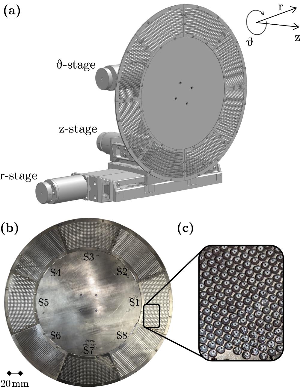
Figure 1.(a) Drawing of the target assembly, depicting the three motorized stages and a rotating wheel. (b) Picture of a target wheel design for 10 Hz operation. (c) Zoomed-in picture of the target wheel, showing the craters on the targets after their irradiation.
The key element of the target assembly is the multi-shot rotating wheel. In our case, the wheel is formed by a base 304-mm-diameter, 2-mm-thick aluminium disk that can be directly attached to the rotational stage, and is capable of hosting up to eight target sectors. The material and thickness of the disk are a compromise between minimizing the overall weight, below the maximum load for the stages, while maximizing the stability and robustness of the structure. Each sector consists of a target foil of choice sandwiched between two planar plates of 400 μm in thickness, with pre-drilled holes that allow the irradiation of the target by the laser (Figure 1(b)). These planar plates allow one to ensure the stability of the foil throughout the operation, avoiding the deformation of the foil in impact positions adjacent to the irradiated targets (Figure 1(c)), which could otherwise result in changes greater than 100 μm. The actual distribution, which sets the maximum repetition rate and number of impact positions of the wheel, is limited by factors such as the maximum speed and range of motion of the stages, as well as the minimum size of and distance between the holes on the sector plates. In order to maximize the number of irradiation points, the pre-drilled holes are distributed along concentric circular patterns, where the diameter of each hole is kept at 2 mm to prevent damage by the laser. The flexibility of the design ensures its compatibility with a broad range of target materials and thicknesses (see
Considering the aforementioned constraints, the maximum repetition rate of operation of the target for a row of the circular pattern at radius
3. Target automatic positioning system
The tolerance for the target positioning is defined by the length in which the laser beam remains focused, given by its Rayleigh length, typically of the order of approximately 10 μm for the focusing optics employed in laser-driven ion acceleration experiments. This accuracy is beyond the intrinsic precision of the target system, limited by factors such as mechanical deformations of the wheel and target foil, or the wobbling associated with the rotational stage. Therefore, some form of positioning system is required in order to ensure the placement of each target on the focal plane without the need for individual alignment.
In our case, we have implemented an automatic correction system based on adjusting the target position according to a detailed 3D mapping of the impact positions of the laser pulses on the target, allowing for operation at higher repetition rates than other methods based on online, live correction procedures. To obtain this pre-map, the coordinates of the desired impact positions on the target wheel are defined by its mechanical design, while the longitudinal coordinate, or displacement along the target normal, is measured with an OptoNCDT ILD1320 position sensor by Micro-Epsilon, with a reproducibility of 1 μm (Figure 2). It should be noted that the sensor cannot operate in vacuum, and therefore the entire wheel characterization must be performed in atmospheric conditions prior to the irradiation. In order to perform the characterization in similar conditions to those found during the irradiation, the process is performed at a rate of
![]()
Figure 2.Picture of the setup used for the validation of the target positioning system.
A pre-map measured using the distance sensor for the wheel in Figure 1(b) is shown in Figure 3(a). Large deviations can be observed between the different shooting positions, with variations greater than 1 mm between different regions of the wheel. Furthermore, these deviations are measured not only between different sectors, but also between consecutive targets within the same sector, indicating a deformation of the target surface probably caused by the procedure to sandwich the target foil between the pre-drilled plates, as pointed out by the greater deviations in the regions away from the edges where the target foil is clamped.
![]()
Figure 3.(a) 3D surface map of the aluminium target foils installed at the multi-target wheel. (b) Surface profile of the first approximately 1000 impact positions before (black curve) and after (red curve) correction. (c) Zoomed-in view of the deviation of the impact positions after the correction shown in (b). Each impact position appears represented by an individual marker, and the straight line shows the 3-point moving average of the deviations.
The information contained in the pre-map can be subsequently used to automatically correct the position of each target. In our case, a control software was developed using LabVIEW to handle the motion of the three motorized stages in the target assembly. In the first step, the system calculates the initial deviation with respect to the desired plane for each impact position, as shown in Figure 3(b) (black line). This information is used to calculate the required combined motion of the stages in order to place the target at the desired plane while ensuring that the impact position remains unchanged.
To validate this technique, a position verification was performed, based on the measurement by the distance sensor of the displacement of the impact positions while the correction was being applied. This process was performed in the same conditions as the real laser irradiations, including the equivalent motion profile for the different stages and operation at a repetition rate of 10 Hz. The results of this procedure for the first approximately 1000 impact positions are shown in Figure 3(b) (red), which clearly indicate an improvement with respect to the original movements without correction. For clarity, the same results are shown with a different scale in Figure 3(c), where the individual measurements by the sensor are depicted by the markers, and the straight line represents a 3-point moving average of the experimental data. The distribution of measurements shows a standard deviation of
It should be noted that, although the developed control system has been shown to be capable of accurately positioning each target at the desired plane, it is crucial to ensure that such a plane corresponds to the focal plane of the laser beam. In our case, this information is fed into the control system by manually bringing one of the targets to the laser focal plane. Different techniques are available for the alignment of solid targets, such as the speckle technique[24], the retro-imaging technique[25,26] and the direct imaging technique[27]. For the results here presented, the latter was used, in which the focal plane of the laser is initially found with a high-magnification imaging system, allowing one to place a back-illuminated target at the same plane by ensuring the same optical system is imaging the rear surface of the target. It should be noted that the imaging system used to establish the reference position was also employed to confirm the validity of the pre-map in vacuum conditions, as well as the lack of deformation of the surface of the surrounding shooting positions after the irradiation of any given target.
4. Proton acceleration at the Laser Laboratory for Acceleration and Applications
4.1. Experimental setup
Laser-driven proton acceleration using the developed rotating wheel target and automatic alignment procedure has been studied experimentally at 10 Hz using the setup schematically depicted in Figure 4. The experiments were performed utilizing the STELA laser system, hosted at the L2A2 (Universidade de Santiago de Compostela)[21,22], which provided p-polarized, 800 nm-wavelength pulses at a repetition rate of 10 Hz, containing energies of up to 0.3 J on target, and compressed to a duration of approximately 40 fs.
![]()
Figure 4.Schematic representation of the experimental setup used at the L2A2.
Inside a vacuum chamber maintained at a pressure of approximately
The laser-driven proton beam was characterized using the time-of-flight (ToF) technique, based on the temporally resolved measurement of the signal produced by the protons reaching a detector placed at a distance of 2 m from the interaction point. In order to prevent the detection of electrons, a dipole magnet was placed along the path to deviate electrons while allowing ions and photons into the detector. The detector consisted of a fast plastic scintillator (NE102A) covering an area of
4.2. Experimental results
The ToF signal measured for 1032 consecutive shots, corresponding to the mapped target points in Figures 3(b) and 3(c), is shown in Figure 5(a), where the line and shaded area represent the average and the standard deviation of the signals, respectively. Two distinct peaks can be identified on the signal. The first peak corresponds to the so-called gamma flash, produced by high-energy photons generated during the laser–plasma interaction, which can be used as a reference time for the arrival of the laser pulses. The second peak in the signal corresponds to the incoming charged particles, protons and heavier ions reaching the scintillator at a later time depending on their energy
![]()
Figure 5.(a) Time-of-flight signal of the laser-driven ions. The line and shaded area represent, respectively, the average and standard deviation of the signal detected for 1032 consecutive shots obtained at 10 Hz. (b) Energy spectrum obtained for the data in (a). The black and red shaded areas indicate the proton energies not transmitting and those partially transmitted with nonlinear transmission, respectively. (c) Evolution of the proton cut-off energy, where each individual marker indicates the peak energy for each irradiation; the dark line shows the 20-period moving average and the shaded area shows the standard deviation of the cut-off energies around the 0.81 MeV mean energy.
The energy spectrum of the ion beam can be reconstructed from the ToF signal. Considering the non-relativistic limit, the detection time and energy can be related through the following expression:
In order to quantify the stability and reproducibility of the ion source, the proton cut-off energy has been extracted from the reconstructed proton spectra, shown in Figure 5(c), where the individual markers represent the cut-off energy for each individual irradiation, and the straight line depicts the 20-point moving average of the data. As can be seen, the points are distributed around a mean cut-off energy of 0.82 MeV, with a dispersion given by the standard deviation of 0.12 MeV, representing approximately 15% of relative dispersion. Although these values support the high reproducibility and stability of the long-term operation of the target wheel and proton source, the dispersion is larger than what would be expected considering the measured reproducibility of the target positioning on the focal plane. However, it should be noted that this variability is identical to that found from the irradiation of manually aligned targets under identical experimental conditions. In particular, an average energy of approximately 0.7 MeV and standard deviation of 0.1 MeV were measured from the irradiation of 70 targets, leading to a 15% dispersion (see
5. Conclusions
Here we have presented a multi-shot target assembly for laser–plasma ion acceleration compatible with multi-hertz operation. The assembly consists of a 3D motorized rig, with one rotational and two linear stages that guarantee the shot-to-shot replenishing and positioning at laser focus of the target material, and a wheel target holder. The rotating wheel is capable of hosting more than 5000 targets and is designed to operate continuously at rates of up to 10 Hz.
An automatic procedure for the alignment of the target surface with respect to the laser focal plane for each impact position has been introduced. This procedure is based on a 3D pre-map of the desired shooting positions obtained prior to irradiation, with an industrial optical sensor with micrometre-level precision. This map of positions, which can be retrieved in a few minutes, can be used to calculate the required correction to ensure the target placement by the software controlling the shot-to-shot movement of the three stages of the target assembly. Following this procedure, we have demonstrated that the individual targets can be positioned at the laser focus with an accuracy of
The target assembly has been successfully used to accelerate ions using the high-power laser system at the L2A2 facility. The laser-driven proton beam has been characterized by means of a ToF detector. A stable, continuous, 10 Hz laser-driven proton source was demonstrated from the irradiation of more than 1000 consecutive targets, exhibiting a mean cut-off energy of 0.82 MeV and relative dispersion of 15%, probably due to the shot-to-shot variations in the laser parameters.
References
[1] H. Daido, M. Nishiuchi, A. S. Pirozhkov. Rep. Progress Phys., 75, 056401(2012).
[2] A. Macchi, M. Borghesi, M. Passoni. Rev. Mod. Phys., 85, 751(2013).
[3] L. Robson, P. T. Simpson, R. J. Clarke, K. W. D. Ledingham, F. Lindau, O. Lundh, T. McCanny, P. Mora, D. Neely, C.-G. Wahlström, M. Zepf, P. McKenna. Nat. Phys., 3, 58(2006).
[4] J. Fuchs, P. Antici, E. d’Humières, E. Lefebvre, M. Borghesi, E. Brambrink, C. A. Cecchetti, M. Kaluza, V. Malka, M. Manclossi, S. Meyroneinc, P. Mora, J. Schreiber, T. Toncian, H. Pépin, P. Audebert. Nat. Phys., 2, 48(2005).
[5] A. Bembibre, A. Alejo, J. Peñas, J. Benlliure. Eur. Phys. J. Web Conf., 290, 08003(2023).
[6] J. T. Morrison, S. Feister, K. D. Frische, D. R. Austin, G. K. Ngirmang, N. R. Murphy, C. Orban, E. A. Chowdhury, W. Roquemore. New J. Phys., 20, 022001(2018).
[7] P. Poole, C. Andereck, D. Schumacher, R. Daskalova, S. Feister, K. George, C. Willis, K. Akli, E. Chowdhury. Phys. Plasmas, 063109(2014).
[8] D. Schumacher, P. Poole, C. Willis, G. Cochran, R. Daskalova, J. Purcell, R. Heery. J. Instrum., 12, C04023(2017).
[9] C. A. J. Palmer, N. P. Dover, I. Pogorelsky, M. Babzien, G. I. Dudnikova, M. Ispiriyan, M. N. Polyanskiy, J. Schreiber, P. Shkolnikov, V. Yakimenko, Z. Najmudin. Phys. Rev. Lett., 106, 014801(2011).
[10] P. Puyuelo Valdés, J. L. Henares, F. Hannachi, T. Ceccotti, J. Domange, M. Ehret, E. d’Humieres, L. Lancia, J.-R. Marquès, J. Santos, M. Tarisien. , , , , , , , , , , and , Proc. SPIE , 110370B ()., 11037(2019).
[11] A. Tebartz, S. Bedacht, M. Hesse, S. Astbury, R. Clarke, A. Ortner, G. Schaumann, F. Wagner, D. Neely, M. Roth. Rev. Sci. Instrum., 88, 093512(2017).
[12] J. Polz, A. P. L. Robinson, A. Kalinin, G. A. Becker, R. A. C. Fraga, M. Hellwing, M. Hornung, S. Keppler, A. Kessler, D. Klöpfel, H. Liebetrau, F. Schorcht, J. Hein, M. Zepf, R. E. Grisenti, M. C. Kaluza. Sci. Rep., 9, 16534(2019).
[13] T. Nayuki, Y. Oishi, T. Fujii, K. Nemoto, T. Kayoiji, Y. Okano, Y. Hironaka, K. G. Nakamura, K.-i. Kondo, K.-i. Ueda. Rev. Sci. Instrum., 74, 3293(2003).
[14] M. Noaman-ul Haq, H. Ahmed, T. Sokollik, L. Yu, Z. Liu, X. Yuan, F. Yuan, M. Mirzaie, X. Ge, L. Chen, J. Zhang. Phys. Rev. Accel. Beams, 20, 041301(2017).
[15] F. P. Condamine, N. Jourdain, J.-C. Hernandez, M. Taylor, H. Bohlin, A. Fajstavr, T. M. Jeong, D. Kumar, T. Laštovička, O. Renner, S. Weber. Rev. Sci. Instrum., 92, 063504(2021).
[16] N. Xu, M. J. V. Streeter, O. C. Ettlinger, H. Ahmed, S. Astbury, M. Borghesi, N. Bourgeois, C. B. Curry, S. J. D. Dann, N. P. Dover, T. Dzelzainis, V. Istokskaia, M. Gauthier, L. Giuffrida, G. D. Glenn, S. H. Glenzer, R. J. Gray, J. S. Green, G. S. Hicks, C. Hyland, M. King, B. Loughran, D. Margarone, O. McCusker, P. McKenna, C. Parisuaña, P. Parsons, C. Spindloe, D. R. Symes, F. Treffert, C. A. J. Palmer, Z. Najmudin. High Power Laser Sci. Eng., e23(2023).
[17] Y. Gao, J. Bin, D. Haffa, C. Kreuzer, J. Hartmann, M. Speicher, F. H. Lindner, T. M. Ostermayr, P. Hilz, T. F. Rösch, S. Lehrack, F. Englbrecht, S. Seuferling, M. Gilljohann, H. Ding, W. Ma, K. Parodi, J. Schreiber. High Power Laser Sci. Eng., e12(2017).
[18] C. Spindloe, G. Arthur, F. Hall, S. Tomlinson, R. Potter, S. Kar, J. Green, A. Higginbotham, N. Booth, M. K. Tolley. J. Phys. Conf. Ser., 713, 012002(2016).
[19] R. Zaffino, M. Seimetz, D. Quirión, A. R. de la Cruz, I. Sánchez, P. Mur, J. Benlliure, L. Martín, L. Roso, J. M. Benlloch, M. Lozano, G. Pellegrini. Microelectron. Eng., 194, 67(2018).
[20] Y. Gershuni, D. Roitman, I. Cohen, E. Porat, Y. Danan, M. Elkind, A. Levanon, R. Louzon, D. Reichenberg, A. Tsabary, E. Urisman, S. Vaisman, I. Pomerantz. Nucl. Instrum. Methods Phys. Res. A, 934, 58(2019).
[21] J. Benlliure, D. Cortina-Gil, J. Llerena, C. Ruiz. Nucl. Instrum. Methods Phys. Res. Sect. A, 916, 158(2019).
[22] A. Alejo, A. Bembibre, J. Peñas, J. Benlliure, L. Martín, M. T. Flores-Arias. Eur. Phys. J. Web Conf., 266, 13001(2022).
[23] T. Chagovets, S. Stanček, L. Giuffrida, A. Velyhan, M. Tryus, F. Grepl, V. Istokskaia, V. Kantarelou, T. Wiste, J. C. Hernandez Martin, F. Schillaci, D. Margarone. Appl. Sci., 11, 1680(2021).
[24] I. Alexeev, J. Wu, M. Karg, Z. Zalevsky, M. Schmidt. Appl. Opt., 56, 7413(2017).
[25] D. Carroll, M. Coury, G. Scott, P. McKenna, M. Streeter, H. Nakamura, Z. Najmudin, F. Fiorini, S. Green, J. Green, P. Foster, R. Heathcote, K. Poder, D. Symes, R. J. Clarke, R. Clarke, R. Pattathil, D. Neely. An assessment of the reproducibility of the Gemini retro focusing system(2011).
[26] D. Kumar, M. Šmd, S. Singh, A. Soloviev, H. Bohlin, K. Burdonov, G. Fente, A. Kotov, L. Lancia, V. Lédl, S. Makarov, M. Morrissey, S. Perevalov, D. Romanovsky, S. Pikuz, R. Kodama, D. Neely, P. McKenna, T. Laštovička, M. Starodubtsev, S. Weber, M. Nakatsutsumi, J. Fuchs. Matter Radiat. Extremes, 024402(2019).
[27] P. K. Singh, K. Kakolee, T. W. Jeong, S. Ter-Avetisyan. Nucl. Instrum. Methods Phys. Res. Sect. A, 829, 363(2016).
[28] M. Seimetz, P. Bellido, A. Soriano, J. García López, M. C. Jiménez-Ramos, B. Fernández, P. Conde, E. Crespo, A. J. González, L. Hernández, A. Iborra, L. Moliner, J. P. Rigla, M. J. Rodríguez-Álvarez, F. Sánchez, S. Sánchez, L. F. Vidal, J. M. Benlloch. IEEE Trans. Nucl. Sci., 62, 3216(2015).


Set citation alerts for the article
Please enter your email address

© Copyright 2018-2021 | Chinese Laser Press. All Rights Reserved 沪ICP备15018463号-20