Abstract
The method for batch continuous production of polymerized cholesteric liquid crystal (PCLC) microdisks based on centrifugal microfluidics was proposed. The prototype centrifugal microfluidic chip was fabricated by the wet-etching technique with a series of ladder-like concentric ring channels whose depths decrease radially. Two types of dye-doped PCLC microdisks with different doping procedures were generated by this method, the tunable lasing properties were characterized, and corresponding potential applications in a micro-cavity laser and optical barcode were demonstrated. The method is also applicable to a broad range of other polymerized materials.The term polymerized cholesteric liquid crystal (PCLC) flakes, was coined by Faris[1] to describe PCLC prepared in the Grandjean texture and fractured into smaller pieces in the order of tens to hundreds of micrometers, which can function as discrete domains and maintain the wavelength and polarization selectivities of original films with environmental stability and electro-optic switching properties[2–4]. PCLC flakes embedded in a suitable host medium analogous to the polymer-dispersed system can provide various passive optical applications in decorative arts, document security, and models of other mixed-media systems without an electric field[1,2]. When suspended in a moderately conductive host fluid, PCLC flakes with the ability to be reoriented or switched that are endowed by an alternating-current (AC) electric field are useful in an unlimited number of potential applications in information displays and photonics and have yet to be conceived[3,5]. PCLC flakes were initially generated by the freeze-fracture technique to make well-aligned macroscopic PCLC polymer films into micrometer-scale pieces with random shapes and sizes[1]. Although this method is convenient to manufacture a large amount of PCLC flakes, the uncontrolled flake shapes have restricted their applications. Since the reorientation time of a flake is dependent upon its shape and size, the methods to produce flakes in controlled shapes and sizes using photolithographic, embossing, or mold replication techniques have been developed more recently to obtain a better understanding of the physics of electro-optical reorientation for PCLC flakes[6]. However, there still exists limitations, e.g., being time-consuming, difficult to achieve high throughput of shaped flakes in these batch processes.
Circular flakes, also named microdisks, are one class of the most commonly shaped flakes. Photonic microdisks made from diverse materials with multiple functions and significant merits have been reported. For instance, the switching of brilliant structural colors was achieved in multilayered microdisks obtained from photocurable suspensions of silica and ferrimagnetic particles[7]. Chip-scale silicon microdisks with smooth surfaces were created as whispering gallery mode (WGM) cavities with dramatically improved cavity Q factors[8]. Wavelength-switchable single-mode lasing was demonstrated as an optimized tangentially coupled cavity system constituted with a vapor-responsive organic microdisk and a perovskite microwire[9]. Consequently, the requirement on continuous production of microdisks is becoming increasingly stringent. As an alternative choice, innovative microfluidic approaches to synthesize particles using droplet-based or flow-lithography-based methods have been proposed to offer prominent application towards continuous fabrication of microdisks bearing a wide variety of chemistries[10,11]. Deformation of spherical droplets in the pressure-driven microfluidic devices with predesigned channel geometries is versatile to generate non-spherical structures including microdisks, owing to surface tension effects, but still limited to handling each droplet one at a time with relatively low efficiency. Fortunately, centrifugal microfluidics, which have been devoted to acting as an advanced miniaturized platform for continuous synthesis of Janus microparticles with high productivity, might have potential application in batch continuous production of microdisks[12]. The exploitation of centrifugal forces in rotating systems was rarely reported to create microflakes. Therefore, there is a need to further examine and evaluate the extended application of centrifugal microfluidics as a meaningful toolkit to fabricate microflakes.
In this work, we report a prototype of a centrifugal microfluidic platform to generate PCLC microdisks as a continuous batch process, rendering it applicable to a broad range of other polymerizable materials. The representative centrifugal microfluidic chip with a series of ladder-like concentric ring channels, whose depths decrease radially, was prepared by the wet-etching technique. Monodispersed droplets of cholesteric liquid crystal (CLC)/polymer dispersions produced by glass-capillary-based microfluidics were loaded in the reservoir at the center of chip, then transported radially outward, driven by centrifugal forces and deformed into microdisks in channels with depths smaller than the diameter of the droplets. Furthermore, the lasing properties of two types of dye-doped PCLC microdisks with different doping procedures were characterized and corresponding potential applications in micro-cavity laser and optical barcode were demonstrated.
Sign up for Chinese Optics Letters TOC. Get the latest issue of Chinese Optics Letters delivered right to you!Sign up now
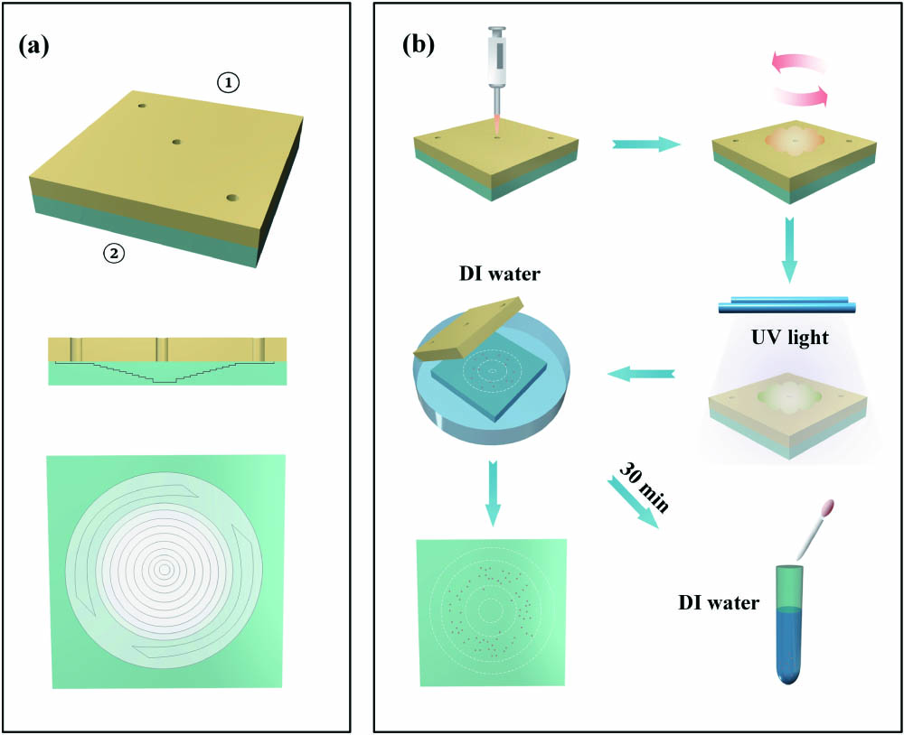
The centrifugal microfluidic chip employed in the experiment consists of an upper polymethyl methacrylate (PMMA) substrate and a bottom glass substrate, as shown in Fig. 1(a). There are three circular through holes drilled in the upper substrate, including the central injection one and two marginal intake ones with the same diameter of about 500 μm. The bottom glass substrate with a ladder-like profile of designed variation was etched by acid solution with the volume ratio of hydrofluoric acid, nitric acid, and deionized (DI) water fixed at 10:7:83, and the etch rate was measured to be about 1.2 μm/min by a step profiler. An adhesive tape with concentric circle patterns carved by a laser engraving machine covered the glass substrate as an anti-acid mask. Then, the carved circular regions on the tape were peeled off manually from the inside ring to the outside ring by forceps. In the meantime, the substrate was immersed into the acid solution for a span of time and cleaned thoroughly using DI water in a step-wise manner. By controlling each etching time, eleven ladder-like concentric ring channels were prepared with the depths decreasing radially. The available thicknesses of the resultant CLC microdisks are determined by the depths of the ring channels. The central channel (first) acted as the reservoir with the maximum depth of around 200 μm, which should be larger than the diameters of the employed CLC droplets. The depths of other ring channels (2nd–11th) decreased from 145 μm to 10 μm with a constant gradient of 15 μm acquired through experimental optimization. If the gradient is too large, the droplets are difficult to be squashed into outer ring channels. In contrast, if the gradient is too small, the production efficiency of microdisks will become extremely low. Then, the upper and bottom substrates were assembled together after the residual of the adhesive tape was removed. A home-made clamp was used to ensure the close bond between two substrates without an air gap. Monodispersed droplets of CLC/polymer dispersions were produced by glass-capillary-based microfluidics and loaded into the reservoir through the central injection hole by a pipette, as depicted in Fig. 1(b). The diameter of droplets should not exceed 200 μm due to the limitation of reservoir depth. Afterwards, the centrifugal chip was mounted on a spin coater, and the droplets were squashed into a disk-like shape driven by centrifugal forces and cured to form PCLC microdisks under the ultraviolet (UV) irradiation with an appropriate dose. After the chip was immersed in DI water for several minutes, two substrates were separated, and the PCLC microdisks that dispersed and suspended in the DI water could be easily collected by a rubber dropper.

Figure 1.(a) Structure diagram of centrifugal microfluidic chip. (b) Schematic fabrication process of PCLC microdisk.
Two types of dye-doped PCLC microdisks with different doping procedures were fabricated for potential applications in laser emissions. The dye used in type I samples was added into CLC/polymer dispersions before droplet formation, while that used in type II samples was doped in the additional washing-out/refilling procedures after UV curing. The dye-doped CLC/polymer dispersions were prepared for type I samples by a mixture of nematic LC E7 (Xianhua, China), chiral dopant R5011 (Xianhua, China), reactive mesogens (RMs mixed by RM257, RM82, RM006, RM021, and RM010 with the mass ratio of 3:2:2:2:1, Xianhua, China), photo-initiator 2,2-dimethoxy-1,2-diphenylethan-1-one (Irgacure 651, Japan), and laser dye 4-dicyanomethylene-2-methyl-6-(p-(dimethylamino) styryl)-4 H-pyran (DCM, Exciton) with mass fractions of 71.79%, 2.21%, 24.0%, 1.0%, and 1.0%, respectively. The mixture was heated up to 75°C and stirred at about 800 r/min by a magnetic stirrer for 20 min to ensure homogeneous mixing. In addition, the CLC/polymer dispersions without dye doping were prepared for type II samples with the mass fraction of RMs slightly increased to 25.0%. Type II samples were obtained after unpolymerized monomers, LC molecules, chiral dopant, and photo-initiator in the PCLC were washed out completely by ethanol, and the remaining porous polymer networks were dried and refilled with the mixture of DCM (1.0%) and E7 (99.0%).
As for the preparation of PCLC microdisks, the rotation rate of the centrifugal microfluidic chip is a key influencing factor. At a relatively high spin speed, the disk-like droplets were easily broken by strong centrifugal force. On the contrary, with a relatively low spin speed, droplets were hard to be squashed into outer ring channels by weak centrifugal force. The experimentally optimized spin speed of 750 r/min was applied in the investigation of other influence factors. To reveal the relationship between the diameter of the initial droplets and the dimensions of the final PCLC microdisks, monodispersed droplets were fabricated for the exploration of type I samples with three diameters of 92 μm, 136 μm, and 180 μm. The corresponding distributions of type I samples in each ring channel of the centrifugal microfluidic chip after rotating for 15 s through microscopic observation are illustrated in Figs. 2(a)–2(c). Over 90% of microdisk samples concentrate in three or four successive ring channels. The microdisks collected from 92 μm droplets were mainly located in the seventh, eighth, and ninth ring channels with the thicknesses of 70 μm, 55 μm, and 40 μm, respectively; those collected from 136 μm droplets were mainly located in the fifth, sixth, seventh, and eighth ring channels with the thicknesses of 100 μm, 85 μm, 70 μm, and 55 μm; while those collected from 180 μm droplets were mainly located in the fourth, fifth, and sixth ring channels with the thicknesses of 115 μm, 100 μm, and 85 μm. The microscopic observation results about the diameters of major microdisk samples were depicted in Fig. 2(d). The diameters of microdisks collected from 92 μm droplets in three main channels are 107 μm (seventh), 120 μm (eighth), and 140 μm (ninth), respectively; the diameters of those collected from 136 μm droplets in four main channels are 163 μm (fifth), 176 μm (sixth), 191 μm (seventh), and 215 μm (eighth); while the diameters of those collected from 180 μm droplets in three main channels are 230 μm (fourth), 245 μm (fifth), and 265 μm (sixth). Figure 2(f) demonstrates the microscopic images of the 180 μm droplet and corresponding microdisks in the fourth, fifth, and sixth ring channels. It is indicated that smaller droplets are more likely to be centrifuged into outer channels. Furthermore, the diameters of microdisks can be fitted by a linear model approximately, which embodies a notable positive correlation between the diameters and the ring channel numbers.
Figure 2.(a)–(c) Distribution of dye-doped PCLC microdisks in each ring channel of centrifugal microfluidic chip and (d) the diameters of microdisks in the main channels for type I samples collected from droplets with diameters of 92 μm, 136 μm, and 180 μm. (e) Simplified physical model to analyze the broken microdisks in the outermost ring channels. (f) Microscopic images of 180 μm droplet and corresponding microdisks in the fourth, fifth, and sixth ring channels. The scale bar is 100 μm.
According to microscopic observation, less than 10% of microdisks assembled in the outermost ring channels and a part of samples broke up into tiny pieces. A simplified physical model shown in Fig. 2(e) is proposed to explain the phenomenon. When a microdisk rotates as a whole in the chip, there must be a centrifugal force, whereas the microdisk only suffers from friction force that can be negligible because the friction coefficient is small enough in the chip. Therefore, the net force is approximately equal to zero and cannot support the circular motion of the microdisk. The microdisk deviates from the center of chip and moves along the direction of velocity, as shown in panel (I), Fig. 2(e). As the squash degree increases, the microdisk begins to split up, which can be regarded as two separating objectives, as illustrated in panel (II), Fig. 2(e). The centrifugal forces can be formulated as and , where is the mass of the microdisk, is the angular frequency, and denotes the rotation radius. Due to the different and , the difference of the two centrifugal forces can be expressed as . In this case, the intermolecular force also should be considered. When is no more than , i.e., , can offset . As a result, the objectives and do not split up and rotate as a whole. When the microdisk continues moving towards outermost ring channels, the squash degree further increases, leading to reducing contact area between and and the decrease of . When is less than , cannot sustain , which results in the splitting of the microdisk.
To characterize the lasing properties of dye-doped PCLC microdisk samples, a Q-switched frequency-doubling Nd-doped yttrium aluminum garnet (Nd:YAG) pulsed laser with a wavelength of 532 nm, repetition rate of 1 Hz, and pulse duration of 12 ns was adopted as the pumping source[13]. The output was modulated to be a linearly-polarized (LP) beam by Glan–Taylor prisms, expanded and collimated by a beam expander with the diameter adjusted using a variable aperture. Then, the pumping beam was reflected by a dichroic mirror and converged to be a focused spot with the diameter of 90 μm by an objective lens (10×, ). The emission was collected by the same objective lens and passed through the same dichroic mirror towards the fiber-optic probe that linked with a spectrometer (HR2000+, Ocean Optics). Meanwhile, the real-time pump energy was monitored by an energy meter. Notably, dye-doped PCLC microdisk samples of types I and II collected from 180 μm droplets were both tested to exclude the influences induced by various sizes of initial droplets.
The lasing properties of dye-doped PCLC microdisk samples of type I are illustrated in Fig. 3. Reflectance spectra of samples gathered from the fourth, fifth, and sixth ring channels manifest a slight blue shift, as shown in Fig. 3(a). The central wavelengths of the reflection band were measured to be 585 nm, 580 nm, and 573 nm, respectively, of which theoretical values can be determined by the formula , where and are the average refractive index (RI) and the helical pitch length. Since all samples were collected from initial droplets with the same diameter of 180 μm, those with a larger channel number have smaller thicknesses and corresponding shorter and . The coincidence between the fluorescence spectrum of DCM and the long band edge of reflectance spectra made laser emissions feasible. The emission spectra of samples gathered from the fourth, fifth, and sixth ring channels when pumped with a fixed pump energy of are recorded in Fig. 3(b) with the lasing peaks occurring at 639 nm, 632 nm, and 602 nm. The full widths at half-maximum (FWHM) were measured to be about 2.1 nm, 1.2 nm, and 0.6 nm. Notably, the corresponding thresholds for samples in three main channels were (fourth), (fifth), and (sixth), as depicted in Fig. 3(c). It is demonstrated that lasing behaviors of dye-doped PCLC microdisks of type I are related to the thicknesses of the samples. The temperature-dependent laser emission spectra of samples in the fifth ring channel are presented in Fig. 3(d) with two-stage regularities. At the first stage, with the temperature rising from 35°C to 45°C, the emission intensity kept on increasing until reaching a certain turning point in connection with the clearing point of unpolymerized LCs. We consider that the lasing at the band edge is related with the density of photon modes. With the increase of temperature, the lifetime of modes at the edge is lengthened, and thus the lasing emission obtains higher gain[14]. At the second stage, when the temperature was further increased, the intensity of the laser emission decreased gradually and disappeared eventually. The phenomenon can be interpreted by the distortion and destruction of the chiral photonic crystal structure when the LC mixture experiences the transition from anisotropy to isotropy.
Figure 3.Lasing properties of dye-doped PCLC microdisk samples of type I collected from 180 μm droplets. (a) Reflectance spectra of samples in three main channels and the fluorescence spectrum of DCM. (b) The laser emission spectra with a fixed pump energy of and (c) lasing thresholds of samples in three main channels. (d) The temperature-dependent laser emission spectra of samples in the fifth ring channel.
Compared with the aforementioned type I samples, the dye-doped PCLC microdisk samples of type II were prepared in a relatively complicated way using additional washing-out/refilling procedures. As shown in Fig. 4(a), the reflectance spectra of type II samples collected in the fifth ring channel from 180 μm droplets were investigated in four consecutive stages during the fabrication process, namely before curing, after curing, after washing out, and after refilling. After UV polymerization, the central wavelength of the reflection band shifted from 637 nm to 557 nm due to polymer cross-linking. In the after-washing-out and after-refilling stages, the reflection band disappeared and reappeared, indicating the deswollen and swollen states, respectively. The inset represents the scanning electron microscope (SEM) images of the polymer network in the after-washing-out stage, revealing the inside nanopores, which would facilitate the refilling process. Undoubtedly they provide the local environment that is required for the incorporation of E7 doped with suitable amount of DCM dye[15]. As shown in Fig. 4(b), the microscopic images recorded in the reflection mode for each stage had structural color changes coincident with wavelength shifts in the reflection band.
Figure 4.(a) Reflection spectra and (b) microscopic images in reflection mode in four consecutive stages (before curing, after curing, after washing out, and after refilling) for dye-doped PCLC microdisk samples of type II in the fifth ring channel collected from 180 μm droplets. The inset in (a) shows SEM images of the PCLC microdisk after washing out with the scale bars of (I) 50 μm and (II) 0.2 μm; the scale bar of (b) is 50 μm.
As shown in Fig. 5(a), the temperature-dependent reflectance spectra of the same type II samples revealed that the reflection band became much narrower as the temperature increased. As illustrated in Fig. 5(b), the corresponding temperature-dependent multi-wavelength laser emission spectra with fixed pump energy of were quite different from that of type I samples. The emission intensity became increasingly stronger when the temperature increased from 35°C to 75°C and started to decrease above 75°C. It is indicated that the turning point of type II samples is significantly higher than that of type I samples due to the relatively high proportion of the polymer network and higher phase-transition temperature in type II samples. Meanwhile, two separated groups of emission peaks were observed at 75°C and 95°C. It can be explained by the overlapping condition of DCM fluorescence spectrum and the narrow reflection band at elevated temperatures. The laser emission was contributed by the short band edge when the temperature approached the turning point[16]. It should be noted that multi-wavelength emission can be identified in type II samples at various temperatures due to the possible slight variation of structure properties in multi-domains with different swollen extents after the refilling procedure. The lasing threshold was measured to be about , which was much lower than that of type I samples [Fig. 5(c)].
Figure 5.Lasing properties of dye-doped PCLC microdisk samples of type II in the fifth ring channel collected from 180 μm droplets. (a) Reflectance spectra of samples at various temperatures and the fluorescence spectrum of DCM. (b) Temperature-dependent laser emission spectra at a fixed position with a fixed pump energy of and (c) lasing thresholds of samples. (d) Potential applications in optical barcodes.
The multi-wavelength laser emission from dye-doped PCLC microdisk samples of type II holds the potential to be employed as a new class of unclonable optical barcodes for various practical applications, such as anti-counterfeiting, and identification[17]. The unique advantages of the optical barcodes based on PCLC microdisks were achieved by encoding the multi-wavelength laser emission excited from a specific location that covered by the pumping beam at a fixed temperature. Specifically, as depicted in panel (I), Fig. 5(d), the pumped location on the microdisk was documented by a polarized optical microscope (POM) in reflection mode. The matching barcode image contained a series of black bars with different widths, which are in association with FWHM values of the laser spectrum measured at room temperature. The locations of the bars correspond to the wavelength of separated lasing peaks with lasing intensity values beyond 100. While the troughs were always uneven, the higher points were chosen as the baseline to calculate FWHMs [panel (III), Fig. 5(d)].
In conclusion, we report the batch production of PCLC microdisks with controllable diameters and thicknesses based on a prototype centrifugal microfluidic chip fabricated by wet etching a series of ladder-like concentric ring channels with radially decreasing depths from inside out. Two types of dye-doped PCLC microdisks with different doping procedures were generated. The tunable lasing properties were characterized and compared. Potential applications as micro-cavity lasers and optical barcodes were demonstrated. It is anticipated that a modified method based on the integration of a droplet-producing microfluidic unit into the current centrifugal microfluidic chip with properly designed outlet holes is also promising to facilitate the batch continuous production for a broad range of other polymerizable materials for advanced photonic applications.
References
[1] S. M. Faris(1994).
[2] E. M. Korenic, S. D. Jacobs, S. M. Fare, L. Li. Mol. Cryst. Liq. Cryst. Sci. Technol., 317, 197(1998).
[3] K. L. Marshall, T. Z. Kosc, S. D. Jacobs, S. M. Faris, L. Li(2003).
[4] H. Lu, C. Wei, Q. Zhang, M. Xu, Y. Ding, G. Zhang, J. Zhu, K. Xie, X. Zhang, Z. Hu, L. Qiu. Photon. Res., 7, 137(2019).
[5] T. Z. Kosc, K. L. Marshall, S. D. Jacobs, J. C. Lambropoulos. J. Appl. Phys., 98, 13509(2005).
[6] A. Trajkovska-Petkoska, R. Varshneya, T. Z. Kosc, K. L. Marshall, S. D. Jacobs. Adv. Function. Mater., 15, 217(2005).
[7] H. S. Lee, J. H. Kim, J. S. Lee, J. Y. Sim, J. Y. Seo, Y.-K. Oh, S.-M. Yang, S.-H. Kim. Adv. Mater., 26, 5801(2014).
[8] Y. Wang, N. Zhang, Z. Jiang, L. Wang, Y. Xiao, W. Sun, N. Yi, S. Liu, X. Gu, S. Xiao, Q. Song. Adv. Mater. Technol., 2, 1600299(2017).
[9] J. Zhao, Y. Yan, C. Wei, W. Zhang, Z. Gao, Y. S. Zhao. Nano Lett., 18, 1241(2018).
[10] D. Dendukuri, P. S. Doyle. Adv. Mater., 21, 4071(2009).
[11] D. Dendukuri, K. Tsoi, T. A. Hatton, P. S. Doyle. Langmuir, 21, 2113(2005).
[12] S. Yoshida, M. Takinoue, H. Onoe, 1267(2015).
[13] W. Li, C. Yang, B. Luo, Z. Y. Wang, X. Z. Wang, Y. K. Bu, S. S. Li, H. Y. Xu, L. J. Chen. Chin. Opt. Lett., 12, 111602(2014).
[14] G. E. Nevskaya, S. P. Palto, M. G. Tomilin. J. Opt. Technol., 77, 473(2010).
[15] J. D. Lin, C. L. Chu, H. Y. Lin, B. You, C.-T. Horng, S.-Y. Huang, T.-S. Mo, C.-Y. Huang, C.-R. Lee. Opt. Mater. Express, 5, 1419(2015).
[16] V. I. Kopp, B. Fan, H. K. M. Vithana, A. Z. Genack. Opt. Lett., 23, 1707(1998).
[17] F. Ramiro-Manzano, R. Fenollosa, E. Xifré-Pérez, M. Garín, F. Meseguer. Nano. Res. Lett., 7, 497(2012).