1College of Microelectronics, Faculty of Information Technology, Beijing University of Technology, Beijing 100124, China
2State Key Laboratory on Integrated Optoelectronics, Institute of Semiconductors, Chinese Academy of Sciences, Beijing 100083, China
3School of Electronic, Electrical and Communication Engineering, Center of Materials Science and Optoelectronics Engineering, University of Chinese Academy of Sciences, Beijing 100049, China
We focus on photonic generation and transmission of microwave signals in this work. Based on dual-pumped stimulated Brillouin scattering, a single-sideband (SSB) optical signal with high sideband rejection ratio is obtained. Combined with a phase-modulated optical carrier, an arbitrarily phase coded microwave signal is generated after photoelectric conversion. The SSB modulation can eliminate the fiber-dispersion-induced power dispersion naturally, and the phase modulation of the optical carrier can achieve arbitrary phase encoding and suppress background noise. The proposed scheme can achieve both generation and anti-dispersion transmission of arbitrarily phase coded signals simultaneously, which is suitable for one-to-multi long-distance radar networking.
Radar detects targets by transmitting and receiving electromagnetic waves and has strong perception and detection capabilities[1]. By phase encoding microwave signals, the signal energy can be more concentrated after matched filtering, which can improve the pulse compression ratio (PCR) of the radar waveform and improve the resolution of the radar system[2]. Microwave photonics has the advantages of high frequency, large bandwidth, reconfiguration, and anti-electromagnetic interference, and thus photonic generation of phase coded microwave signals has become a hot topic[3].
Various photonic assisted approaches have been reported to generate phase coded microwave signals. Frequency-time mapping can achieve arbitrary waveform generation[4]. However, the pulse rate and time duration of the generated signals are restricted by the used spectral shaper. In direct space-time mapping technology, a spatial modulator is always involved, which makes the signal generator lossy and environment sensitive[5]. Encoding the relative phase of two optical signals is the key to optical heterodyne[6]. By equivalently switching the direct current (DC) bias of the Mach–Zehnder modulator (MZM) at positive and negative quadrature points, phase coded microwave signals can be generated[7]. Based on optical carrier phase shifting, binary phase coded microwave signals are produced after photodetection[8]. Phase coded microwave signals can also be generated by using cascaded modulators, parallel modulators, and cross polarization modulation effect[9–11]. However, these schemes only demonstrated the generation of phase encoding. Actually, an arbitrarily phase coded microwave signal has the advantages of good periodic correlation and large Doppler tolerance, which is also crucial for radar systems[12]. The polarization division multiplexing modulators can generate two orthogonally polarized optical sidebands. By aligning the two sidebands to the two principal axes of a cascading polarization modulator (PolM), arbitrarily phase coded microwave signals can be produced[13]. A fiber Bragg grating and phase modulator involved Sagnac loop can also realize arbitrary phase encoding[14]. In addition, in modern radar networks, the radar signals generated by the central station need to be transmitted to different remote base stations through long-distance optical fibers. However, during fiber transmission, fiber dispersion will introduce different phase shifts to optical signals and cause power fading[15]. Therefore, there is an urgent need to establish a radar signal transmitter that can realize arbitrarily phase coded signal generation and anti-dispersion transmission.
In this Letter, we propose a photonic transmitter that can generate arbitrarily phase coded microwave signals and eliminate power fading. By making use of the gain spectrum and attenuation spectrum of the dual-pump stimulated Brillouin scattering (SBS), the st-order sideband of the radio frequency (RF) carrier-modulated optical signal is amplified, while the st-order sideband optical signal is decreased, thereby obtaining a single-sideband (SSB)-modulated optical signal with high rejection ratio. When the SSB-modulated optical signal and the phase-modulated optical carrier are sent to a photodetector (PD), an arbitrarily phase coded microwave signal can be generated, whose center frequency corresponds to the driven RF carrier, and whose bit rate and phase format agree with the driven coding signal. In addition, the generated SSB-modulated optical signal can transform the phase introduced by fiber dispersion to the phase rather than the amplitude of the recovered microwave signal in the remote base station so that power fading can be eliminated. The proposed scheme has promising applications in one-to-multi radar networks.
Sign up for Chinese Optics Letters TOC. Get the latest issue of Chinese Optics Letters delivered right to you!Sign up now
2. Principle
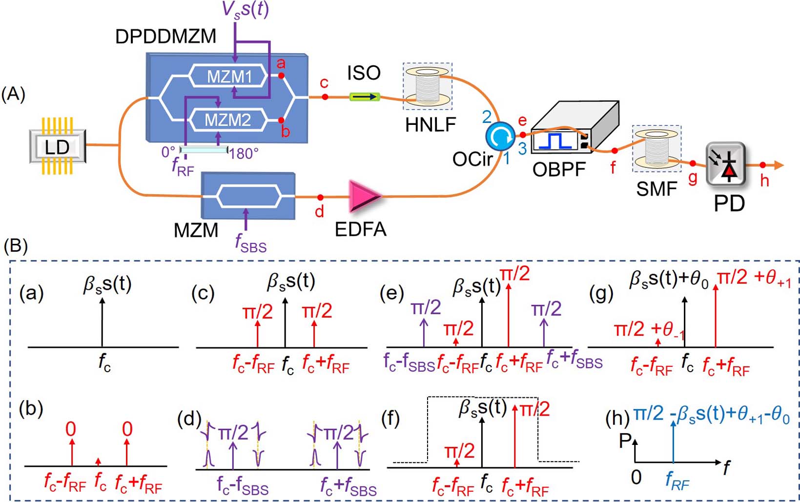
Figure 1(A) shows the schematic diagram of the proposed system. The optical carrier emitted from a laser diode (LD) is split into two paths. The upper path constitutes the arbitrarily phase coded signal generation, and the lower path realizes the SBS dual-pumped optical signal generation. A dual-parallel dual-drive MZM modulator (DPDDMZM), which consists of MZM1 and MZM2 parallel to each other, is the key component of the upper path. An electrical coding signal is first divided into two parts by an electrical power coupler. Afterwards, the obtained two identical coding signals are sent to the two RF input ports of MZM1. Therefore, the output optical signal of MZM1 can be expressed as where and are the amplitude and frequency of the optical carrier, and are the peak-to-peak amplitude and format of the electrical coding signal, is the modulation index of the coding signal, is the DC bias introduced phase shift of MZM1, is the DC bias voltage, and is the half-wave voltage of MZMs. By setting the DC bias voltage of MZM1 at 0 V, the output optical signal of MZM1 can be given by
Figure 1.(A) Schematic diagram and (B) principle of the proposed SBS-based arbitrarily phase coded microwave waveform transmitter.
Thus, a phase-modulated optical carrier is generated, as illustrated in Fig. 1(B-a). At the same time, an RF carrier is first applied to a 180° hybrid coupler to produce two RF signals with 180° phase difference. Then, the two RF signals are sent to MZM2, which is biased at the minimum transmission point. At the output of MZM2, a carrier suppressed double sideband (CS-DSB)-modulated optical signal is generated, as shown in Fig. 1(B-b) and the following equation: where , , and are the frequency, amplitude, and modulation index of the RF carriers, and is the first-order Bessel function of the first kind. After being combined in DPDDMZM, the output optical field can be given by
It can be seen from Eq. (4) that a phase-modulated optical carrier with two RF-modulated optical sidebands are obtained, as shown in Fig. 1(B-c). Meanwhile, a microwave carrier at frequency of drives the MZM in the lower path. By setting the MZM at a minimum transmission point, the output optical field is given by where , , and are the frequency, amplitude, and modulation index of the driven SBS-microwave signal. An erbium-doped fiber amplifier (EDFA) is cascaded after the MZM to boost the power of the optical signal. The amplified optical signal is coupled into a spool of highly nonlinear fiber (HNLF) through an optical circulator to work as the two SBS pumped signals. The gain factor and loss factor of the SBS can be described as where and are the line-center gain factor and Brillouin gain bandwidth of the HNLF, and are the frequency deviation from and , respectively. The first term of the gain factor and loss factor can be regarded as an amplitude coefficient, and the second term can be seen as a phase coefficient. By adjusting the frequency of the SBS-microwave carrier (), the gain spectrum of the sideband amplifies the RF-modulated st-order sideband, while the loss spectrum of the sideband decreases the RF-modulated st-order sideband. As shown in Fig. 1(B-d), the spectral lines at the lower left and upper left of the two SBS sidebands represent the amplitude and phase responses of the SBS-gain spectrum, while the spectral lines at the lower right and upper right of the SBS sidebands represent the amplitude and phase responses of the SBS attenuation spectrum. The optical signal after the SBS effect can be expressed as where , is the Brillouin frequency shift. The amplitude amplification factor , amplitude attenuation factor , and phase shift factor are defined as
By setting , the amplitude amplification factor reaches the maximum, amplitude attenuation factor reaches the minimum, and phase shift factor is equal to zero. Thus, the optical signal after the SBS effect can be written as
Therefore, an SSB optical signal with high rejection ratio is obtained, as illustrated in Fig. 1(B-e). An optical bandpass filter (OBPF) is cascaded to remove the SBS pump signals. After being transmitted over a long-distance fiber, the optical signal in the remote base station can be expressed as where and are the dispersion-induced phase shifts to the RF-modulated st-order optical signal and the optical carrier. By expanding the propagation constant in Taylor series, we have where is the transmitted distance. Afterwards, the optical signal is detected by a PD. The recovered microwave signal is expressed as
According to Eq. (13), a phase coded microwave signal with a carrier frequency of is generated. The encoding format is the same as the driven electrical signal , which means that arbitrary phase coding is realized. The signal amplitude is also independent of the fiber dispersion. Therefore, the generation and anti-dispersion of arbitrarily phase coded microwave signals are achieved simultaneously in this work.
3. Experiments and Results
A proof-of-concept experiment was performed according to the scheme shown in Fig. 1(A). A 1549.97 nm optical carrier is divided into two parts by an optical coupler. In the upper path, a 16-bit 2 Gb/s electrical coding signal generated from a pattern pulse generator (PPG) with pattern of 0001001101011111 is applied to the upper input ports of the DPDDMZM. The amplitude of the electrical coding signal is equal to the half-wave voltage of the DPDDMZM. An 8 GHz RF signal is first sent to a 180° hybrid coupler and then fed to the lower input port of the DPDDMZM. By setting the two sub-MZMs of the DPDDMZM at maximum and minimum transmission points, a phase-modulated optical carrier plus an RF-modulated DSB signal is obtained, which can be seen from the measured optical spectrum of Fig. 2(a). In the lower path, an MZM is driven by an SBS-microwave signal centered at 17.42 GHz and biased at a minimum transmission point. Figure 2(b) shows the measured optical spectrum. A CS-DSB optical signal is generated and will work as the dual-pumped light to stimulate the SBS in the HNLF. The HNLF used in this experiment has a length of 500 m and Brillion frequency shift of 9.42 GHz. Figure 2(c) shows the optical spectrum at the output of the HNLF. Compared with the st-order sideband, the st-order optical sideband is suppressed more than 35 dB, which is much higher than conventional SSB modulation[16]. The sideband ratio between st-order and nd-order sidebands is also much higher than that of conventional SSB modulation, which can increase the spurious free dynamic range (SFDR) of the system. Moreover, the power of the st-order sideband is 10 dB higher than that of the optical carrier, which can improve the signal-to-noise ratio (SNR) of the generated microwave signal. Thus, an SSB optical signal with high gain and high sideband rejection ratio is obtained after the process of dual-pumped SBS. It should be noted that the obtained optical signal is not just a simple SSB-modulated signal. The optical carrier is phase-modulated, which cannot be realized in conventional SSB schemes. After the HNLF, an OBPF is cascaded to remove the useless SBS pump light and the SBS noise. The filtered optical spectrum is shown in Fig. 3(d). Finally, the optical signal is sent to a PD to perform the square rate detection.
Figure 2.Measured optical spectra at the output of (a) DPDDMZM, (b) MZM, (c) HNLF, and (d) OBPF.
Figure 3.(a) Time-domain waveform, (b) extracted phase information, (c) electrical spectrum, and (d) autocorrelation of the generated π phase coded microwave signal with RF carrier of 8 GHz and bit rate of 2 Gb/s.
Figure 3(a) shows the measured time-domain waveform of the generated phase coded microwave signal. The discontinuousness in the waveform illustrates the phase jump of the waveform. By using Hilbert transform, the phase information is extracted from the waveform and is shown in Fig. 3(b). The phase coded degree and pattern are and 0001011001011111, which are consistent with the driven coding signal. Figure 3(c) shows the corresponding electrical spectrum. The center frequency is 8 GHz, which fits well with the applied RF carrier, and the main lobe covers the frequency of 6–10 GHz, which is also consistent with the bit rate of the driven coding signal. Background noise is not visible in the electrical spectrum, so crosstalk with other signals can be avoided, and additional filtering processing is no longer required to filter out background noise commonly found in phase coded signals. Also, no baseband-modulated components in the generated waveform can be evidenced by the fact that the center amplitudes of different parts of the waveform are flush with each other. In order to show the pulse compression performance, the autocorrelation of the waveform is calculated and shown in Fig. 3(d) with an insert zoom-in view. The peak-to-sidelobe ratio (PSR) is 6.93 dB, the full width at half-maximum (FWHM) is 0.513 ns, and the PCR is 15.60. Next, the amplitude of the driven electrical coding signal is adjusted to verify the arbitrary phase coding performance. Figure 4 shows the waveform and the extracted phase coding information of the generated microwave waveforms. The phase coding degrees of 130°, 80°, and 30° are achieved successfully, and the coding sequences fit well with the driven electrical coding signals.
Figure 4.(a), (c), (e) Time-domain waveform and (b), (d), (f) extracted phase information of the generated 2 Gb/s at 8 GHz phase coded microwave signal with phase coding degrees of 130°, 80°, and 30°, respectively.
For purpose of verifying the anti-dispersion transmission over a single-mode fiber (SMF) of the proposed arbitrarily phase coded microwave generator, a 25 km SMF is cascaded after the OBPF as the transmission link. Figures 5(a)–5(c) show the waveform, phase information, and autocorrelation of the recovered 2 Gb/s at 8 GHz phase coded microwave signal after 25 km SMF transmission. The phase encoded information is undistorted and remains the degree of . The PSR, FWHM, and PCR are, respectively, 7.40 dB, 0.525 ns, and 15.24. Although the amplitude of the waveform is decreased, it is caused by the insertion loss of the used 25 km SMF rather than the dispersion introduced power fading. In order to support this point of view, we used an optical attenuator whose attenuation is the same as the insertion loss of the SMF to replace the 25 km SMF. The measured time-domain waveform, phase information, and autocorrelation result are illustrated in Figs. 5(d)–5(f). The waveform amplitude is almost the same as that in Fig. 5(a). The phase shifting is also . According to the autocorrelation, the recovered phase coded microwave waveform has a PSR of 7.64 dB, an FWHM of 0.515 ns, and a PCR of 15.53. Therefore, the power fading caused by fiber dispersion in transmission is well eliminated.
Figure 5.(a), (d) Time-domain waveform, (b), (e) extracted phase information, and (c), (f) autocorrelation of the recovered 2 Gb/s at 8 GHz π phase coded signal after 25 km SMF transmission and optical attenuator.
In order to show the frequency tunability of the proposed arbitrarily phase coded microwave signal transmitter, we changed the frequency of the RF carrier, the bit rate of the driven coding signal, and the frequency of the SBS-microwave signal to 16 GHz, 4 Gb/s, and 25.42 GHz, respectively. The measured time-domain waveform is shown in Fig. 6(a), and obvious phase jump can be obtained. The center amplitudes of different components in the waveform are also equal. The extracted phase information in Fig. 6(b) confirms the phase coding. Figure 6(c) shows the electrical spectrum of the phase coded signal, where the frequency range of the main lobe is 12–20 GHz that agrees well with the 16 GHz RF carrier and 4 Gb/s driven coding sequence. The pulse compression performance is also calculated. A PSR of 4.76 dB, an FWHM of 0.204 ns, and a PCR of 19.61 are obtained from Fig. 6(c). By adjusting the peak-to-peak amplitude of the driven electrical coding signal, the phase coding degree can also be changed accordingly. The 4 Gb/s at 16 GHz phase encoded microwave signals with encoding degrees of 130°, 80°, and 30° are obtained, as illustrated in Figs. 6(d)–6(i).
Figure 6.(a) Time-domain waveform, (b) extracted phase information, (c) electrical spectrum, and (d) autocorrelation of the generated π phase coded microwave signal with RF carrier of 16 GHz and bit rate of 4 Gb/s. (e), (g), (i) Time-domain waveform and (f), (h), (j) extracted phase information of the generated 4 Gb/s at 16 GHz phase coded microwave signal with phase coding degrees of 130°, 80°, and 30°, respectively.
Similarly, we added a spool of 25 km SMF into the system as a transmission link to demonstrate the anti-dispersion transmission performance of the signal generator. Figure 7(a) shows the measured waveform of the phase coded microwave signal in the remote base station, where phase jump can be seen obviously. Based on Hilbert transmission, the phase information is exhibited in Fig. 7(b). The phase coding is realized, and the sequence is also 0001011001011111. Figure 7 shows the pulse compression performance. The PSR, FWHM, and PCR are, respectively, 4.74 dB, 0.246 ns, and 16.26. Next, the SMF is replaced by an optical attenuator with attenuation equal to the SMF insertion loss. The waveform and extracted phase information are shown in Figs. 7(d) and 7(e), which are quite similar to Figs. 7(a) and 7(b). From the autocorrelation of Fig. 7(f), it can be seen that the PSR of the recovered phase coded microwave signal is 4.84 dB, the FWHM is 0.240 ns, and the PCR is 16.67. The similarity of the experimental results after transmitting 25 km fiber and after passing through the optical attenuator shows that the proposed phase coded signal generator can achieve long-distance anti-dispersion transmission. It should be noted that the driven electrical coding signals were first amplified by an electrical amplifier (EA) and then sent to the modulator. The EA may introduce noise to the electrical coding signal, which degrades the extracted phase information. If a high-linearity low-noise amplifier can be used, the phase ripples/distortions of the extracted phase information will be reduced. Moreover, the phase distortion is also related to the power of the phase coded microwave signals. After transmitting 25 km SMF or passing through an optical attenuator, the power of the recovered phase coded signal was decreased. By increasing the responsibility of the PD or adding an amplifier, the amplitude of the generated and recovered phase coded signals can be improved, thereby reducing the phase distortion.
Figure 7.(a), (d) Time-domain waveform, (b), (e) extracted phase information, and (c), (f) autocorrelation of the recovered 4 Gb/s at 16 GHz π microwave signal after 25 km SMF transmission and optical attenuator, respectively.
In conclusion, we have theoretically analyzed and experimentally demonstrated an SBS-based arbitrarily phase coded microwave waveform generator with anti-dispersion transmission. Thanks to the gain and attenuation spectrum of the dual-pumped SBS, a high rejection ratio SSB-modulated optical signal is obtained. The phase modulation of the optical carrier can not only realize the arbitrary format encoding of the generated microwave signal, but also ensure that the generated waveform has no interference from background noise. Different phase coding degrees of the generated microwave waveform are achieved. The tunability of the carrier frequency and bit rate are also performed. The proposed generator has a great promising aspect in one-to-multi modern radar networks.
References
[1] D. K. Barton. Modern Radar System Analysis(1988).
[2] N. Levanon. Radar Principles(1988).
[3] J. Capmany, D. Novak. Microwave photonics combines two worlds. Nat. Photonics, 1, 319(2007).
[4] J. Ye, L. Yan, Z. Chen, W. Pan, B. Luo, X. Zou, S. Yao. Photonic generation of microwave phase-coded signals based on frequency-to-time conversion. IEEE Photon. Technol. Lett., 24, 1527(2012).
[5] J. D. McKinney, D. E. Leaird, A. M. Weiner. Millimeter-wave arbitrary waveform generation with a direct space-to-time pulse shaper. Opt. Lett., 27, 1345(2002).
[6] S. Zhu, X. Fan, M. Li, N. Zhu, W. Li. Photonic generation and transmission of phase-modulated microwave signals. Proc. SPIE, 11182, 111820B(2019).
[7] Z. Tang, T. Zhang, F. Zhang, S. Pan. Photonic generation of a phase-coded microwave signal based on a single dual-drive Mach–Zehnder modulator. Opt. Lett., 38, 5365(2013).
[8] C. Song, M. Lei, J. Qian, Z. Zheng, S. Huang, X. Gao. All-optical generation of binary phase-coded microwave pulses without baseband components based on a dual-parallel Mach–Zehnder modulator. Opt. Express, 27, 20064(2019).
[9] H. Jiang, L. Yan, J. Ye, W. Pan, B. Luo, X. Zou. Photonic generation of phase-coded microwave signals with tunable carrier frequency. Opt. Lett., 38, 1361(2013).
[10] S. Liu, D. Zhu, Z. Wei, L. Pan. Photonic generation of widely tunable phase-coded microwave signals based on a dual-parallel polarization modulator. Opt. Lett., 39, 3958(2014).
[11] W. Li, W. Wang, W. Sun, N. Zhu. All-optical generation of binary phase coded microwave signal based on cross-polarization modulation in a highly nonlinear fiber. Opt. Lett., 39, 1561(2014).
[12] D. Chu. Polyphase codes with good periodic correlation properties. IEEE Trans. Inf. Theory, 18, 531(1972).
[13] Y. Zhang, F. Zhang, S. Pan. Generation of frequency-multiplied and phase-coded signal using an optical polarization division multiplexing modulator. IEEE Trans. Microw. Theory and Techn., 65, 651(2016).
[14] X. Li, S. Zhao, Z. Zhu, K. Qu, T. Lin, S. Pan. Frequency-octupled phase-coded signal generation based on carrier-suppressed high-order double sideband modulation. Chin. Opt. Lett., 15, 070603(2017).
[15] A. Nirmalathas, P. A. Gamage, C. Lim, D. Novak, R. Waterhouse, Y. Yang. Digitized RF transmission over fiber. IEEE Microw. Mag., 10, 75(2009).
[16] Y. Bai, M. Lei, Z. Zheng, J. Qian, X. Song, Z. Su, S. Huang. Wideband and dispersion immune microwave photonic phase shifter with tunable optical carrier to sideband ratio. J. Light. Technol., 38, 5262(2020).