• Chinese Optics Letters
  • Vol. 15, Issue 9, 091901 (2017)
Chuanyi Zhu, Yuping Chen*, Guangzhen Li, Licheng Ge, Bing Zhu, Mengning Hu, and Xianfeng Chen
Author Affiliations
  • State Key Laboratory of Advanced Optical Communication Systems and Networks, School of Physics and Astronomy, Shanghai Jiao Tong University, Shanghai 200240, China
  • show less
    DOI: 10.3788/COL201715.091901 Cite this Article Set citation alerts
    Chuanyi Zhu, Yuping Chen, Guangzhen Li, Licheng Ge, Bing Zhu, Mengning Hu, Xianfeng Chen. Multiple-mode phase matching in a single-crystal lithium niobate waveguide for three-wave mixing[J]. Chinese Optics Letters, 2017, 15(9): 091901 Copy Citation Text show less
    (a) Schematic diagram of LN thin film. The blue light line represents the light beam at 1018 nm propagating in the planar waveguide. (b) A sectional view of the waveguide and propagation of guiding mode waves. (c) Mode field distributions when the thicknesses of the film are 300 and 900 nm, respectively. (d) The mode size versus different thicknesses of the film.
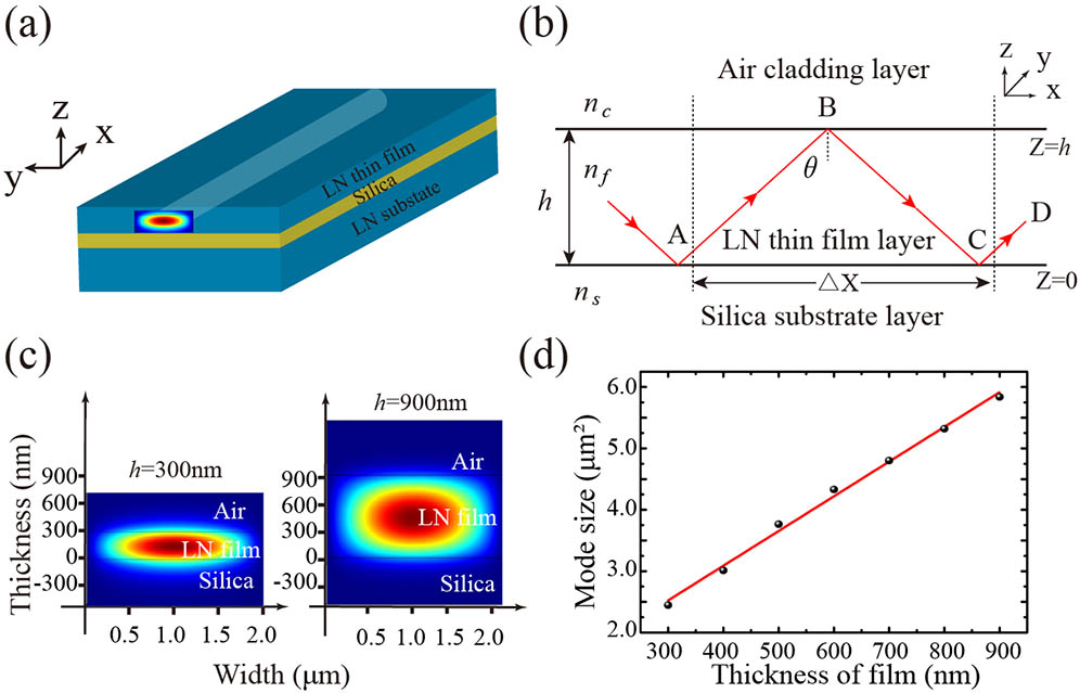
    Fig. 1. (a) Schematic diagram of LN thin film. The blue light line represents the light beam at 1018 nm propagating in the planar waveguide. (b) A sectional view of the waveguide and propagation of guiding mode waves. (c) Mode field distributions when the thicknesses of the film are 300 and 900 nm, respectively. (d) The mode size versus different thicknesses of the film.
    (Color online) Dispersion relation of TE- and TM-polarized modes for (a) FW and (b) SH waves in LN thin film with different thicknesses at 25°C. h1, h2, h3, h4, h5, and h6 represent thicknesses of the layers, which are 500, 600, 700, 800, 900, and 1000 nm, respectively.
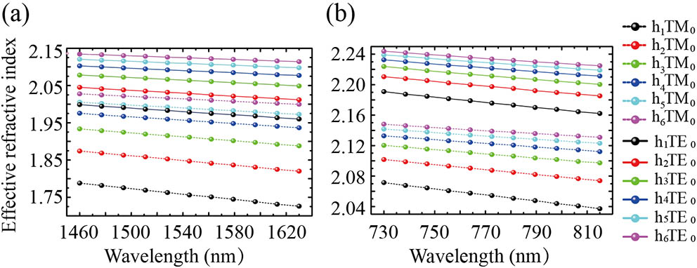
    Fig. 2. (Color online) Dispersion relation of TE- and TM-polarized modes for (a) FW and (b) SH waves in LN thin film with different thicknesses at 25°C. h1, h2, h3, h4, h5, and h6 represent thicknesses of the layers, which are 500, 600, 700, 800, 900, and 1000 nm, respectively.
    (Color online) Three-mode phase-matching diagrams in 900 nm LN thin film: (a) o+o→o; (b) o+o→e; (c) e+e→e. The solid and dashed lines represent FW and SH waves, respectively, and the black, red, blue, and green lines represent the 0th, 1st, 2nd, and 3rd orders of the space guiding modes. The black points on the intersection stand for nonoverlapping of the space-mode field distribution for the FW and SH waves. The red points stand for the simultaneous satisfaction of the space-mode overlapping and phase-matching modes of the FW and SH waves. (d) The wavelength of the phase-matching point between the 0th FW and 2nd SH waves varies almost linearly with the thickness of the thin film.
    Fig. 3. (Color online) Three-mode phase-matching diagrams in 900 nm LN thin film: (a) o+oo; (b) o+oe; (c) e+ee. The solid and dashed lines represent FW and SH waves, respectively, and the black, red, blue, and green lines represent the 0th, 1st, 2nd, and 3rd orders of the space guiding modes. The black points on the intersection stand for nonoverlapping of the space-mode field distribution for the FW and SH waves. The red points stand for the simultaneous satisfaction of the space-mode overlapping and phase-matching modes of the FW and SH waves. (d) The wavelength of the phase-matching point between the 0th FW and 2nd SH waves varies almost linearly with the thickness of the thin film.
    (Color online) (a) Type II mode phase matching for SHG: e+ o→o, where the FW is 1.55 μm with both the TE- and TM-polarized modes, SH is 0.775 μm with the TE-polarized mode. (b) A schematic of SHG (e+o→o) and SPDC (o→e+o).
    Fig. 4. (Color online) (a) Type II mode phase matching for SHG: e+oo, where the FW is 1.55 μm with both the TE- and TM-polarized modes, SH is 0.775 μm with the TE-polarized mode. (b) A schematic of SHG(e+oo) and SPDC(oe+o).
    (Color online) Mode phase matching SHG experiment. (a) The sketch of the experimental setup. (b) The top view of the green light field captured by the camera. (c) The spectra of the input pulse laser and the output SH light at 509 nm (for the 1018 nm pump light), respectively. (d) The quadratic intensity relationship between the TM-polarized SH and FW waves.
    Fig. 5. (Color online) Mode phase matching SHG experiment. (a) The sketch of the experimental setup. (b) The top view of the green light field captured by the camera. (c) The spectra of the input pulse laser and the output SH light at 509 nm (for the 1018 nm pump light), respectively. (d) The quadratic intensity relationship between the TM-polarized SH and FW waves.
    Chuanyi Zhu, Yuping Chen, Guangzhen Li, Licheng Ge, Bing Zhu, Mengning Hu, Xianfeng Chen. Multiple-mode phase matching in a single-crystal lithium niobate waveguide for three-wave mixing[J]. Chinese Optics Letters, 2017, 15(9): 091901
    Download Citation