1Key Laboratory of Photoelectronic Imaging Technology and System, Ministry of Education of China, Beijing 100081, China
2School of Optoelectronics, Beijing Institute of Technology, Beijing 100081, China
3Department of Materials Science and Engineering, Erik Jonsson School of Engineering and Computer Science, University of Texas at Dallas, Richardson, Texas 75083, USA
We experimentally demonstrate a 750 Mb/s real-time visible light communication (VLC) system based on non-return-to-zero on–off keying modulation by employing single commercially available monochromatic light-emitting diodes. To enhance the 3-dB bandwidth of the VLC link, we propose a low-complexity cascaded post-equalizer based on NPN transistors. With two different frequency-selecting networks in our post-equalizer, the highest achieved 3-dB bandwidth of the VLC link is 370 MHz. The highest achieved data rate is 750 Mb/s at a communication distance of 170 cm with a bit error rate below , which is far below the forward error correction limit (). Based on our monochromatic VLC system, a wavelength-division multiplexing VLC system could be designed with a higher data rate.
Light-emitting diodes (LEDs) can be used for both illumination and communication simultaneously and are considered an ideal source for visible light communication (VLC)[1,2]. With wavelength-division multiplexing (WDM) technology considered as an important, promising approach to immensely improve the data rates of VLC systems[3–5], using monochromatic LEDs to achieve multichannel communication and white lighting has gradually attracted researchers’ attention[6].
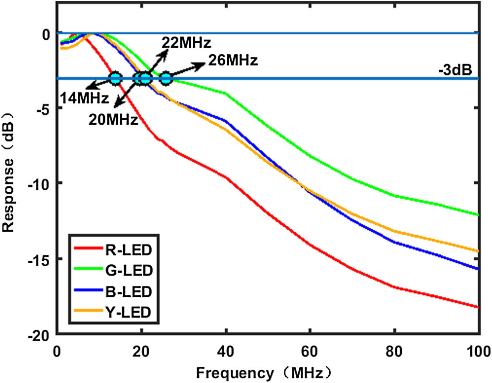
Monochromatic LEDs have finite bandwidths. Figure 1 shows the frequency response of four commercially available monochromatic LEDs belonging to the color LED family of LUXEON Rebel. They could be a good choice for a light source in a WDM-VLC system, for they have superior power efficacy, color stability, flux density, and color saturation. However, all of the 3-dB bandwidths are . Various driving modulation technologies can be used to further increase the bandwidths and equalization technology is one effective ones and was first used by Minh et al. in 2008. They proposed a pre-equalizer to increase the bandwidth of a VLC system to 45 MHz and achieved an 80 Mb/s data rate with non-return-to-zero on–off keying (NRZ-OOK) modulation[7]. After that, various equalizers was proposed and improved, and they had a better performance[8–12]. In 2013, a 151 MHz bandwidth and 340 Mb/s real-time data rate were achieved by using a post-equalization circuit that contained two passive equalizers and one active equalizer[10]. In 2014, by utilizing pre-emphasis and post-equalization circuits, a 3-dB bandwidth of a VLC link was extended from 3 to 233 MHz with a blue filter and a 550 Mb/s real-time data rate was achieved[12]. In 2015, with a cascaded pre-equalizer, the 3-dB bandwidth of a VLC system was improved from 17 to 366 MHz, which is the highest 3-dB bandwidth achieved so far[13]. The highest real-time data rate of 622 Mb/s was reported based on a blue LED by adopting a pre-equalization circuit and post-equalization circuit simultaneously with a 112 MHz 3-dB bandwidth. However, its communication distance was only 15 cm[14].
Figure 1.Frequency response of four commercially available monochromatic LEDs. R-LED: red LED (LXM2-PD01-0050); G-LED: green LED (LXML-PM01-0100); B-LED: blue LED (LXML-PB02); Y-LED: yellow LED (LXML-PL01-0060).
In this Letter, we propose a low-complexity post-equalizer based on NPN transistors to enhance the 3-dB bandwidth of VLC systems and experimentally demonstrate a 750 Mb/s real-time VLC system based on NRZ-OOK modulation by employing a single commercially available monochromatic LED. With two different frequency-selecting networks in the low-complexity cascaded post-equalizer, the 3-dB bandwidths of VLC links employing four different monochromatic LEDs are enhanced effectively, and their 3-dB bandwidths are 370, 347, 272, and 238 MHz for red, green, blue, and yellow LEDs, respectively. Using a bit error rate (BER) test, their real-time data rates are 750, 690, 730, and 650 Mb/s, respectively, at a communication distance of 170 cm with a BER below . In addition, the communication distance is longer than the VLC system mentioned above, and it is more relevant to the actual distance between the light source and desktop in a room. To our knowledge, 370 MHz and 750 Mb/s are the highest 3-dB bandwidth and the highest real-time data rate, respectively, ever achieved by using a post-equalizer and a monochromatic LED. Furthermore, based on our VLC system, if several monochromatic LEDs are used simultaneously in a white LED source, a much higher data rate WDM-VLC system can be expected. If other complex modulation technologies are used at the same time, the data rate can be further improved.
Sign up for Chinese Optics Letters TOC. Get the latest issue of Chinese Optics Letters delivered right to you!Sign up now
Comparing the proposed equalizers, passive RC-based equalizers will decrease the sensitivity of the receiver. Amplifier-based equalizers can increase the power of signal, but the finite gain bandwidth product (GBP) of amplifiers limits their performance at a high frequency range. Transistor-based equalizers not only can increase the power of signal but also have better performance at a high frequency range, for they usually have a high transition frequency. There have been several transistor-based equalizers proposed in recent years, used as pre-equalizers or post-equalizers, such as the pre-equalizer in Ref. [12]. Though the cascaded pre-equalizer enhances the 3-dB bandwidth of a VLC link from 3 to 233 MHz with a post-equalizer, its same frequency-selecting networks limit the 3-dB bandwidth from being further enhanced. To achieve a higher 3-dB bandwidth, we proposed a two-cascaded NPN transistors-based post-equalizer with two different frequency-selecting networks, shown in Fig. 2. The two-stage amplifying structure with different frequency-selecting networks can not only easily adjust the frequency response of the post-equalizer and compensate for the two different high-frequency points of a VLC link via setting the proper parameters, but it will also ensure the phase of the signal output is the same as that of the input signal. Between these two transistor amplifier circuits, a capacitor is used as a blocking capacitor; it is large enough (such as 10 μF) to ensure it will have little influence on the AC signals.
Figure 2.Proposed two-cascaded NPN transistors-based post-equalizer with different frequency-selecting networks.
In the first-stage amplifier circuit, , , and constitute the first frequency-selecting network which can initially adjust the frequency responses. The response function of the first stage amplifier circuit can be expressed by Therefore, the amplitude response function is When is zero, we know the DC gain is , and when is large enough, the amplitude gain will converge at a certain constant .
According to Eq. (2), the 3-dB point above the DC gain can be computed as
From Eqs. (2) and (3), the magnitude response of the first-stage amplifier circuit can be calculated.
In the second-stage amplifier circuit, there is a different frequency-selecting network constituted by and . It is set to compensate for a higher frequency range of the system. The response function of the second-stage amplifier circuit could be expressed by and the amplitude response function is Obviously, the DC gain is , and the 3-dB point above the DC gain can be computed as Equation (5) shows that the amplitude response of the second-stage amplifier circuit is approximately linear versus frequency , which differs from that of the first stage, which converges at a certain constant. Therefore, at a certain high frequency range, the second-stage amplifier structure will have a better amplitude gain than the first-stage amplifier structure, which can compensate well for the weak response of the LEDs.
Thus, the total AC gain of the two-cascaded NPN transistors-based post-equalizer is In our proposed post-equalizer, the high-frequency triode BFR520 (transition frequency: 9 GHz) was used as the transistor. According to impedance matching principle, the input impedance and output impedance were both set at 50 Ω. The value of was set much smaller than because in this case, it would have little influence on the first corner frequency on the basis of Eq. (3) and still have a significant effect on the amplitude response of the circuit according to Eq. (2). Therefore, the 3-dB frequency point of the first-stage amplifier circuit can be estimated according to Eq. (3). In order to obtain a high 3-dB frequency point, the value of can be set small, but it will cause the signal to be excessively restrained. Therefore, the value of was set to not only compensate for the low frequency range, but also to enhance the high frequency range. Meanwhile, it is necessary to set a proper static operating point of the high-frequency triode. The proper parameters for the post-equalizer are listed in Table 1. As these four LEDs have different frequency responses, the set parameters are also different.
LED
R-LED
G-LED
B-LED
Y-LED
R1, R6
150 Ω
150 Ω
150 Ω
150 Ω
R2, R7
75 Ω
75 Ω
75 Ω
75 Ω
R3, R8
100 Ω
83 Ω
83 Ω
100 Ω
R4, R9
100 Ω
83 Ω
83 Ω
100 Ω
R5
10 Ω
11 Ω
7 Ω
11 Ω
C1
5 pF
12 pF
15 pF
9 pF
C3
100 pF
100 pF
100 pF
100 pF
VCC
7.8 V
7.8 V
7.8 V
7.8 V
Table 1. Proper Parameters in Post-Equalizers for LEDs
The setup of the proposed monochromatic LED-based VLC system is shown in Fig. 3. As is shown in Fig. 3(a), at the transmitting terminal, the signal generated by a signal generator was firstly processed by a power amplifier (Mini-Circuits ZHL-6 A-S+, 500 MHz bandwidth). Then, the amplified signal was superimposed onto the LED bias current, supplied by a DC power, via a bias tee (Mini-Circuits ZFBT-4R2GW+, 4200 MHz bandwidth). The hybrid output of the bias tee was directly supplied to the monochromatic LED. A 18° full opening angle collimating lens was fixed in front of the LED at an appropriate distance to ensure the light transmits directionally. Meanwhile, at the receiving terminal, a designed receiving antenna was fixed in front of the detector, whose specifications are shown in Table 2. These two lenses constituted an optical system helping to ensure the high communication performance of the VLC system. The detector was an avalanche photodiode (APD) detector (Menlo System, FPD 310-FV), which had a 900 MHz transition frequency. Another power amplifier was used to amplify the light current outputted by the APD. Then, the signal was improved by a post-equalization process using the proposed post-equalizer. Finally, a signal analyzer followed to analyze the communication performance. Based on the block diagram, we set up the VLC experimental link, shown in Fig. 3(b), whose communication distance is up to 1.7 m.
Figure 3.(a) The block diagram of our VLC system and (b) the VLC experimental link.
Based on the VLC experimental link in Fig. 3(b), we firstly performed measurements for the frequency responses of the four monochromatic LEDs and tested the performances of the proposed post-equalizers. In the measurements, an arbitrary waveform generator (Agilent N9310A) was used as a signal generator, and an MXA signal analyzer (Agilent N9020A) was used as the signal analyzer. The frequency responses of post-equalizers and LEDs with and without post-equalizers are shown in Fig. 4.
Figure 4.Frequency responses of post-equalizers and monochromatic LED-based VLC link with and without post-equalizers: (a) R-LED, (b) G-LED, (c) B-LED, and (d) Y-LED.
The frequency response curves of the post-equalizer in Fig. 4 indicate that our proposed post-equalizer has an excellent ability to restrain the low frequency response and enhance the high frequency response, which can compensate for the frequency response of each monochromatic LED at a large frequency range. However, because of the high suppression characteristic at low frequency ranges, our post-equalizer cannot be cascaded. Otherwise, the signal-to-noise ratio at a low frequency range would be too low to have a good communication performance. To ensure the preciseness and accuracy of the experiments, the 3-dB bandwidth is correctly defined as the 3-dB frequency point, where the power of the spectral response reduces by 3 dB compared with the maximum frequency response value. Therefore, the 3-dB points of monochromatic LED-based VLC links with and without post-equalizers can be read directly from Fig. 4. Just as shown in Fig. 4, all frequency response curves of monochromatic LED-based VLC links without post-equalizers drop in frequency rapidly at a low frequency range, and all of their 3-dB points are . In comparison, all of the 3-dB point of VLC link with post-equalizer are . With the proposed post-equalizers, the 3-dB bandwidth of the R-LED is extended from 14 to 370 MHz, that of the G-LED is extended from 26 to 347 MHz, that of the B-LED is extended from 20 to 272 MHz, and that of the Y-LED is extended from 22 to 238 MHz.
A BER measurement as a function of the data rate to evaluate the communication performance of the monochromatic LED-based VLC systems followed. Based on the VLC experimental link in Fig. 3(b), we used a signal analyzer (Tektronix BITALYZER1600) as both a signal generator and a signal analyzer. The BITALYZER1600 generated a pseudo-random binary sequence-7 () OOK-NRZ data stream with a peak-to-peak voltage swing of 400 mV, whose data rate ranged from 1 to 800 Mb/s. The measured BER experiment results of the four monochromatic LEDs are shown in Fig. 5.
Figure 5.BER versus data rate of monochromatic LED-based VLC links with post-equalizer.
From Fig. 5, we know the VLC system we set up performed well at a data rate below 550 Mb/s, where the BER is no more than . With a BER below , the achieved highest data rates of these LED-based VLC links can be as high as 750 Mb/s, which is the highest data rate in a VLC system using a monochromatic LED based on NRZ-OOK modulation at a communication distance of 170 cm. Both the data rate and communication distance are better than the best reported data. For the R-LED, the BER is at a data rate of 750 Mb/s; for the G-LED, the BER is at a data rate of 690 Mb/s. For the B-LED, the BER is at a data rate of 730 Mb/s, and for the Y-LED, the BER is at a data rate of 650 Mb/s. Their eye diagrams are also shown in Fig. 6. From the measured results, we know that the B-LED-based VLC link with a lower 3-dB bandwidth of 272 MHz still has a higher data rate of 730 Mb/s when its BER is below . In generally, the data rate achieved is not only related to the 3-dB bandwidth of the VLC link but also has a relationship with the signal amplitude of the receiver. The received signal amplitude is also influenced by several factors, such as the spectrum characteristic of the optical antennas, the spectrum response of the APD, and the performance of the post-equalizers. More studies are needed to elucidate how these factors have an effect on data rates. Based on our monochromatic LED-based VLC systems, if several monochromatic LEDs of appropriate colors are used simultaneously as a white lighting source and a communication system, a WDM-VLC system can be designed and a higher data rate will be expected. If other complex modulation technologies, such as OFDM or MIMO, are used as well, the data rate can be further improved. White LED lighting sources can be made by combining RGB or RGBA monochromatic LEDs. When these white light sources are used as WDM-VLC systems simultaneously, one of the major challenges is channel crosstalk because of spectra overlap. We are currently looking into the issue to find out ways to minimize the data rate loss from crosstalk.
Figure 6.Eye diagrams of monochromatic LED-based VLC system with proposed post-equalizer at different data rates with a BER below : (a) R-LED at 750 Mb/s, (b) G-LED at 690 Mb/s, (c) B-LED at 730 Mb/s, and (d) Y-LED at 650 Mb/s.
In conclusion, we propose a two-cascaded NPN transistors-based post-equalizer with two different frequency-selecting networks for a VLC system using single monochromatic LEDs. With the proposed low-complexity post-equalization circuit, the 3-dB bandwidths of the VLC links employing four different monochromatic LEDs are enhanced effectively, and the highest 3-dB bandwidth is 370 MHz. By a BER test, the highest real-time data rate based on NRZ-OOK modulation is 750 Mb/s at a communication distance of 170 cm with a BER below , which is far below the forward error correction limit (). To our knowledge, 370 MHz and 750 Mb/s are the highest 3-dB bandwidth and the highest real-time data rate ever achieved, respectively, by using a post-equalizer and a monochromatic LED. In addition, the communication distance is longer than the VLC system mentioned above, and it is relevant to the actual distance between the light source and desktop in a room. Furthermore, based on the VLC system we experimentally demonstrated, if several monochromatic LEDs are used as light sources simultaneously, a high data rate WDM-VLC system can be designed, and the data rate can be higher. If additional complex modulation technologies, such as OFDM and MIMO, are used simultaneously, the data rate can be improved further.
References
[1] Z. Ghassemlooy, W. Popoola, S. Rajbhandari. Optical Wireless Communication(2013).
[2] H. L. Minh, D. O’Brien, G. Faulkner, L. Zeng, K. Lee, K. Lee, D. Jung, Y. Oh. IEEE Photon. Technol. Lett., 20, 1243(2008).
[3] Y. Wang, R. Li, Y. Wang, Z. Zhang. Proceedings of Optical Fiber Communications Conference and Exhibition, TH1F.1(2014).
[4] G. Cossu, A. M. Khalid, P. Choudhury, R. Corsini, E. Ciaramella. Opt. Express, 20, B501(2012).
[5] Y. Wang, X. Huang, L. Tao, J. Shi, N. Chi. Opt. Express, 13626(2015).
[6] Y. Wang, L. Tao, X. Huang, J. Shi, N. Chi. IEEE Photon. J., 7, 7904507(2015).
[7] H. L. Minh, D. O’Brien, G. Faulkner, L. Zeng, K. Lee, D. Jung, Y. Oh. ECOC, 5, 223(2008).
[8] H. L. Minh, D. O’Brien, G. Faulkner, L. Zeng, K. Lee, D. Jung, Y. Oh, E. T. Won. IEEE Photon. Technol. Lett., 21, 1063(2009).
[9] H. Li, X. Chen, J. Guo, D. Tang, B. Huang, H. Chen. Chin. Opt. Lett., 12, 100604(2014).
[10] H. Li, X. Chen, B. Huang, D. Tang, H. Chen. IEEE Photon. Technol. Lett., 26, 119(2014).
[11] B. Yu, H. Zhang, H. Dong. Chin. Opt. Lett., 12, 110606(2014).
[12] H. Li, X. Chen, J. Guo, H. Chen. Opt. Express, 20203(2014).
[13] X. Huang, Z. Wang, J. Shi, Y. Wang, N. Chi. Opt. Express, 22034(2015).
[14] N. Fujimoto, S. Yamamoto. Proc. ECOC, 2014, 1(2014).