


Xiaoqiang Zhang, Ruishan Chen, Yong Zhou, Hai Ming, Anting Wang, "Mode selective coupler for optical vortices generation (Invited Paper)," Chin. Opt. Lett. 15, 030008 (2017)
- Chinese Optics Letters
- Vol. 15, Issue 3, 030008 (2017)
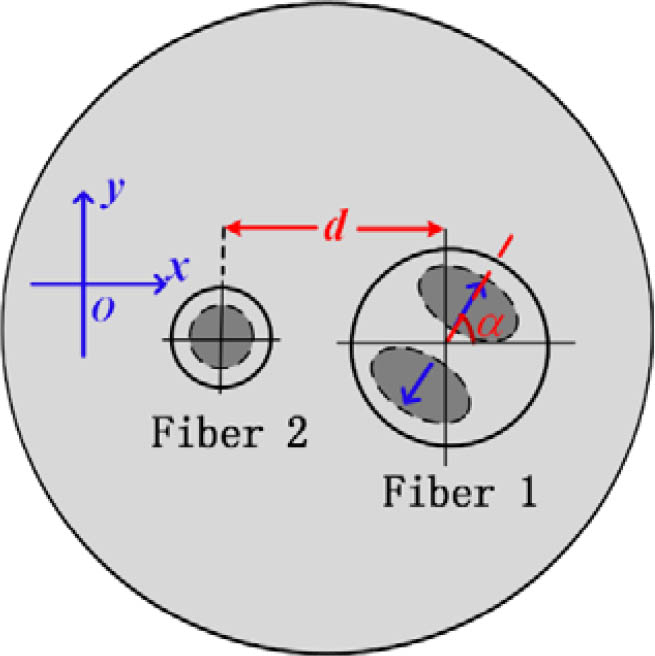
Fig. 1. Cross section of an MSC. Fiber 1 is an MMF, fiber 2 is an SMF, and they have the same cladding. The distance between them is d
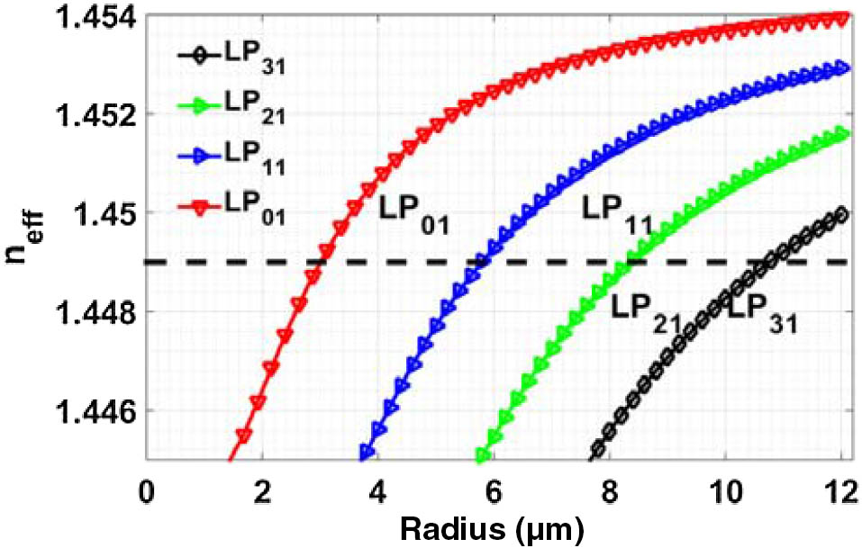
Fig. 2. Effective refractive indices of the modes in a fiber. The dashed line is phase matched between different modes at n eff = 1.449 n co = 1.4546 n cl = 1.4446
Fig. 3. Relative coupling coefficient between fiber 1 and fiber 2 as a function of the azimuthal angle α
Fig. 4. Cross section of the three-core MSC; fiber 2 and fiber 3 are SMFs, and fiber 1 is an MMF. θ
Fig. 5. (a) Normalized coupled power between fiber 2 (LP 01 LP 11 s LP 01 LP 11 c P 2 P 3 P 1 z c = 1.51 cm
Fig. 6. (a) Normalized coupled power between fiber 2 (LP 01 LP 31 s LP 01 LP 31 c P 2 P 3 P 1 z c = 4.92 cm
|
Table 1. Mode Patterns Formed in Fiber 1 by Various Phase Differences of Input Modes in SMFs


Set citation alerts for the article
Please enter your email address

© Copyright 2018-2021 | Chinese Laser Press. All Rights Reserved 沪ICP备15018463号-20