Abstract
We report on our high-contrast laser based on high-contrast, high-energy seed injection, low-gain optical parametric chirped pulse amplification (OPCPA), and Nd:glass amplifiers, which can be used as the high-contrast front end of a high-power Nd:glass chirped pulse amplification (CPA) laser system. The energy of the stretched 1053 nm high-contrast seed pulse increases to 60 μJ by optimizing the frequency doubling crystal in the pulse cleaning device. After passing through a two-stage low-gain OPCPA, a 2-pass 2-rod Nd:glass amplifier, and a compressor the amplified pulse of is achieved. The third-order correlation scanning measurement shows that the pulse contrast in the tens of ps range is about . With the high-contrast seed passing through the stretcher and compressor only, the contrast measurement indicates that the stretching-compressing process leads mainly to the contrast degradation of the amplified pulse.Ever since chirped pulse amplification (CPA)[1] technology was used to amplify ultrashort pulses, the peak power of a CPA laser system has been increased to PW () level[2–6]. With such high power, the focal plane intensity will easily reach or even higher. Under such an extreme focusing condition, the coherent laser emission or prepulses could be intense enough to destroy the physical conditions of the experimental target before the main pulse arrives.
To avoid this situation, pulses with high temporal contrast are required. However, in the case of seeding from an oscillator directly, the pulse temporal contrast in a CPA laser system is usually limited by the amplified spontaneous emission (ASE) in the amplification process because of low-energy and low-contrast of the seed pulses. Therefore, several pulse temporal cleaning techniques have been used at the end of the laser systems, such as plasma mirror (PM)[7] and frequency doubling (FD)[8]. These techniques have been proven to be effective for improving pulse contrast, but high energy loss causes by cleaning process could not be compensated, which seriously decreases the peak power of the pulse. Therefore, many temporal precleaning techniques were used to generate high-contrast seed pulses, such as saturable absorbers (SAs)[9], cross polarized wave generation (XPW)[10], and short pulse optical parametric amplification (OPA)[11,12]. Usually, by high-contrast high-energy seed injection, the ASE could be suppressed efficiently in the amplification process. Therefore, a high-contrast high-power pulse could be obtained in Ti:sapphire CPA systems[13,14]. Recently, high-contrast output was also demonstrated in a 1 μm diode-pumped Yb material laser system[15]. However, it is still a challenge to acquire a high-contrast amplified pulse in Nd:glass CPA systems[16].
Another factor deteriorating the pulse contrast is the prepulse generation. It is difficult to avoid pre- and postpulses generated by surface reflections of optical components in a CPA system, especially in a regenerative amplifier (RA)[17]. Moreover, the prereplicas of the postpulses will also be generated at the other side of the main pulse because of the B-integral accumulated in the amplification process[18]. Therefore, it is crucial to avoid pre- and postpulses and to reduce the B-integral in a CPA system for high-contrast amplification.
Sign up for Chinese Optics Letters TOC. Get the latest issue of Chinese Optics Letters delivered right to you!Sign up now
In the previous work, we developed a 1053 nm pulse cleaning device that was pumped with an 800 nm Ti:sapphire CPA laser[19]. The clean seed pulse was further amplified in the second CPA laser and a high-contrast pulse was obtained with ASE noise suppressed below the level of while there was a big pedestal before the main pulse[20].
When the pulse contrast is considered, optical parametric chirped pulse amplification (OPCPA) has two main advantages compared with regenerative amplification. First, high single-pass gain in OPCPA could effectively reduce the total B-integral accumulated in a system. Second, the simple, compact layout of OPCPA makes it possible to avoid the pre- and postpulse generation. However, for OPCPA, to obtain high-contrast amplification, low gain amplification is required to suppress parametric fluorescence (PF)[21]. Moreover, high-energy pulse injection is also essential for effectively exacting energy from the pump. In this work, we demonstrate our 1053 nm high-contrast amplification based on an OPCPA-Nd:glass laser setup. First, to increase the effective seed injection, we improved the energy of the clean pulse and optimized its spectral bandwidth to well match the transmission bandwidth in the 1053 nm CPA stage. Second, to simplify the laser system and to reduce the B-integral, a two-stage OPCPA preamplifier was used to replace the previous RA. Third, the contrast of the amplified pulse was measured and the results showed that the contrast in the range of tens of ps before the main pulse was enhanced to about compared with our reported result[20]. Finally, the further contrast measurement with the high-contrast seed passing through the stretcher and compressor only indicated that the stretching and compressing process led to the contrast degradation of the amplified pulse.
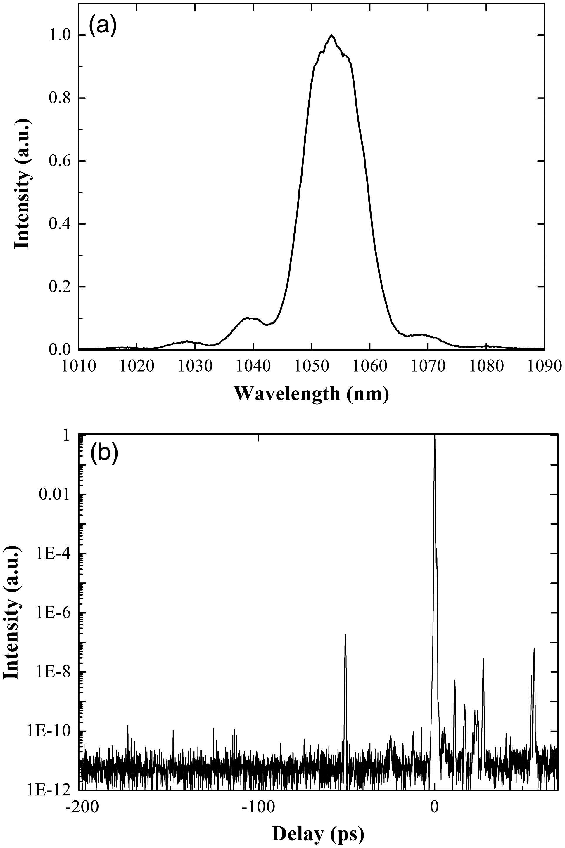
In the previous work[19,22], we built a 1053 nm high-contrast pulse cleaning device based on OPA and second-harmonic-generation (SHG) process pumped with a commercial Ti:sapphire CPA laser. The energy of the clean pulse had decreased to about 70 μJ because the OPA layout mismatched slightly and the energy of the 800 nm pump laser also decreased. In this device, we used a 0.5 mm-thick type-I -barium borate (BBO) crystal as the SHG crystal to generate 1053 nm seed pulses. Usually, a thin SHG crystal leads to a broadband spectrum and low output energy. Considering the limited transmission bandwidth in the 1053 nm CPA stage, a broad bandwidth would decrease the effective energy of the stretched pulse. Low signal injection would lead to low amplification in OPCPA and especially it could not suppress the PF generation under the condition of a high intensity pump. With a fundamental frequency injection (2106 nm) of 450 μJ, the SHG output (1053 nm) increased to 220 μJ after 4 mm-thick type-I BBO was used. Most of the energy was concentrated in a bandwidth of about 20 nm near the Nd:glass gain peak (1053 nm), as shown in Fig. 1(a). The scanning cross correlation measurement (Sequoia-1000, Amplitude Technologies) showed that the contrast was about [Fig. 1(b)].

Figure 1.Output characteristics of the improved pulse cleaning seed: (a) spectrum and (b) third-order correlation contrast measurement.
The schematic diagram of the hybrid double CPA laser system was shown in Fig. 2. The first CPA stage was a commercial 1 kHz 800 nm Ti:sapphire CPA laser. In the second (1053 nm) CPA stage, the cleaning seed pulse was injected into the Offner triplet stretcher. Limited by the size of the grating, the full transmission bandwidth of the stretcher was about 18 nm as shown in Fig. 3. The output energy of the stretcher was 60 μJ which was improved by one order compared with our preresult[20], corresponding to a whole transmission of 27%. The stretched pulse duration was about 1.1 ns (FWHM). After the stretcher, a Faraday isolator was used to prevent surface reflections from the following amplifiers to destroy optics in the stretcher. The beam was up-collimated to 4 mm in diameter to match the pump beam size.
Figure 2.Schematic of the hybrid double CPA laser system. HWP: half-wave plate; QWP: quarter-wave plate; DM: dichroic mirror; TFP: thin film polarizer; HR: high-reflective mirror.
Figure 3.Spectra of the stretched pulse (black line), the pulse after OPCPA (red line), and the amplified compressed pulse (blue line).
Two OPCPA stages were used as the preamplifier to replace the RA in our hybrid double CPA system[20]. In the first OPCPA stage, the BBO crystal was used, and the one was used in the second stage. Both crystals were cut at 22.85° for type-I phase matching. The output faces were also cut with a 0.5° wedge to avoid postpulse generation and to suppress intracavity oscillation. The pump source for the OPCPA was a single longitudinal mode 532 nm, 10 Hz -switched Nd:YAG laser (Quanta-Ray lab-150, Spectra-Physics) with a maximum output of 230 mJ and a pulse duration of 5.5 ns. The pump beam was down-collimated to 4 mm in diameter through a vacuum image relay telescope and a 400 μm pinhole was used to filter off the high-frequency modulation over the beam profile. To reduce PF, a low pump energy of 160 mJ (corresponding to pump power of ) was used to keep the OPA process working at a nonsaturated state[21]. The internal noncollinear angle between the pump beam and signal beam was about 0.67°. The output energy from the first stage was 6 mJ. The signal pulse and the pump pulse were separated by dichroic mirrors. The residual pump energy was used to pump the second OPCPA stage and in the second stage the pump pulse had an extra 1.1 ns delay compared with the signal. Thus, the signal pulse could be amplified by different time parts of the pump pulse in two stages. The output energy of the second stage was 15 mJ with a total gain of 300 in the two OPCPA stages. The output stability was limited mainly by the time jitter between the pump pulse and the seed pulse and the beam profile of the OPCPA was seriously affected by the poor pump beam profile. In the near future, we plan to build a new pump laser seeded by a stable CW single longitudinal mode laser to reduce the time jitter and to improve the homogeneity of the pump beam. The amplified spectrum of the OPCPA (Fig. 3) showed that the OPCPA was operated on a nonsaturated state.
To improve the homogeneity of the beam profile, the beam was expanded by a Galileo expander, and then a 4 mm homogeneous beam was picked out with a round serrated-tooth apodizer. After passing through a Faraday isolator, the beam was up-collimated to 8 mm in diameter and a pinhole was used to filter off high frequency components. After beam homogenization, 2.1 mJ of energy was remained.
The filtered pulse was injected into the 2-pass Nd:glass amplifier. A 90° quartz rotator was used between two Nd:glass modules to reduce the thermal depolarization loss. The beam divergence was optimized by changing the operating frequency, adjusting the voltage of the flashlamps and selecting the appropriate curvature radius of the convex mirror. To reduce the B-integral in the Nd:glass amplifier, the circular polarization was generated by inserting a plate before the first glass module to reduce the effective nonlinear index of the gain glass[23]. After 2-pass amplification, the pulse energy increased to 180 mJ at a repetition rate of 0.5 Hz.
The amplified pulse was sent into the two-grating test compressor and the 282 fs compressed pulse was obtained (Fig. 4). The transmission of the compressor was about 73%, with an output of 131 mJ and the output stability of the whole system was about 2.3% rms (Fig. 5), which made the scanning contrast measurement possible.
Figure 4.Measured autocorrelation trace of the amplified compressed pulse.
Figure 5.Stability of the amplified compressed pulses.
The contrast of the compressed pulse was measured by the scanning third-order autocorrelator. The scanning curve was shown in Fig. 6 with the OPCPA preamplifier. The curve of the OPCPA-Nd:glass amplified pulse showed three characteristics in different time ranges: (i) in the range before , the measured contrast was about , which was limited by the dynamic range of the measuring device; (ii) in the range from to the main pulse, the contrast curve rose quickly, which was decided by the dispersion of the system; (iii) in the range from to , the contrast curve rose slowly. Compared with the pulse’s contrast amplified by a RA (see Ref. [17]), the contrast was enhanced more than one order. For the OPCPA: first, the B-integral of the OPCPA could almost be ignored because of its high single-pass gain; thus, the accumulated B-integral of the system was very low (lower than 0.2 in our case); second, because the layout of the OPCPA was simple and the optical components were cut with a wedge to avoid postpulses, there was no obvious pre- and postpulses; third, the nonsaturated OPCPA suppressed the instantaneous gain saturation effect due to which the prepulses could also be generated by postpulses[24]. Therefore, a better temporal contrast could be achieved in the OPCPA-Nd:glass system and we did not see any evident influence of the high-frequency pump noise that would deteriorate the amplified pulse contrast in the OPCPA[25].
Figure 6.Third-order correlation contrast measurements of the amplified compressed pulse (black line) and the pulse passed through the stretcher and compressor only (red line).
The slow rise over the range from to in the contrast curve of the OPCPA much degraded the pulse contrast. To find its origin, the 4-pass stretched high-contrast seed was directly sent into the compressor without passing through the OPCPA and the Nd:glass amplifier. The residual pulse energy was low (about 55 μJ) after the compressor, which limited the dynamic range of the measurement device to about 10 orders. However, it still obviously showed that the red contrast line was similar to that of the amplified pulse (Fig. 6). Therefore, we could conclude that the stretcher and compressor led mainly to the contrast degradation of the amplified pulse.
There were two possible factors in the stretcher and compressor that would affect the pulse contrast: the wavefront error and the roughness of the optics surface[26]. In the case of the wavefront error of optics, it is well known that it leads to low-frequency spectral phase noise in a stretcher or compressor that mainly broadens the pulse duration, thus degrading the contrast in the several ps range[26,27]. However, the roughness of the optics would lead to high-frequency spectral phase modulations that would produce a low-intensity pedestal around the main pulse over a long time range[28]. Recently, it was demonstrated theoretically[29] and experimentally[30] that this phase noise also exhibits spatiotemporal coupling in the far field, and the application of higher-quality optics showed that it could reduce the high-frequency noise and improve the contrast[31].
In conclusion, we optimize our OPA pulse cleaning device to generate a high-energy seed pulse with a matched bandwidth at 1053 nm. With the high-energy seed pulse injecting, the pulse is amplified in a two-stage OPCPA preamplifier and a 2-pass 2-rod Nd:glass amplifier. The scanning contrast measurement shows that the amplified pulse contrast ratio is improved to in the tens of ps range before the main pulse. With the high-contrast seed passing through the stretcher and compressor only, the contrast measurement indicates that the stretching-compressing process leads mainly to the contrast degradation of the amplified pulse.
References
[1] D. Strickland, G. Mourou. Opt. Commun., 55, 447(1985).
[2] J. H. Sung, S. K. Lee, T. J. Yu, T. M. Jeong, J. Lee. Opt. Lett., 35, 3021(2010).
[3] M. Perry, D. Pennington, B. Stuart, G. Tietbohl, J. Britten, C. Brown, S. Herman, B. Golick, M. Kartz, J. Miller. Opt. Lett., 24, 160(1999).
[4] X. Liang, Y. Leng, C. Wang, C. Li, L. Lin, B. Zhao, Y. Jiang, X. Lu, M. Hu, C. Zhang. Opt. Express, 15, 15335(2007).
[5] E. W. Gaul, M. Martinez, J. Blakeney, A. Jochmann, M. Ringuette, D. Hammond, T. Borger, R. Escamilla, S. Douglas, W. Henderson. Appl. Opt., 49, 1676(2010).
[6] C. Danson, P. Brummitt, R. Clarke, J. Collier, B. Fell, A. Frackiewicz, S. Hancock, S. Hawkes, C. Hernandez-Gomez, P. Holligan. Nucl. Fusion, 44, S239(2004).
[7] G. Doumy, F. Quéré, O. Gobert, M. Perdrix, P. Martin, P. Audebert, J. Gauthier, J.-P. Geindre, T. Wittmann. Phys. Rev. E, 69, 026402(2004).
[8] C. Danson, D. Neely, D. Hillier. High Power Laser Sci. Eng., 2, e34(2014).
[9] J. Itatani, J. Faure, M. Nantel, G. Mourou, S. Watanabe. Opt. Commun., 148, 70(1998).
[10] A. Jullien, O. Albert, F. Burgy, G. Hamoniaux, J.-P. Rousseau, J.-P. Chambaret, F. Augé-Rochereau, G. Chériaux, J. Etchepare, N. Minkovski. Opt. Lett., 30, 920(2005).
[11] C. Dorrer, I. Begishev, A. Okishev, J. Zuegel. Opt. Lett., 32, 2143(2007).
[12] S. Zhong-Wei, W. Zhao-Hua, Z. Wei, F. Hai-Tao, T. Hao, W. Zhi-Yi. Chin. Phys. Lett., 31, 014207(2014).
[13] Z. Wang, C. Liu, Z. Shen, Q. Zhang, H. Teng, Z. Wei. Opt. Lett., 36, 3194(2011).
[14] T. J. Yu, S. K. Lee, J. H. Sung, J. W. Yoon, T. M. Jeong, J. Lee. Opt. Express, 20, 10807(2012).
[15] M. Hornung, H. Liebetrau, A. Seidel, S. Keppler, A. Kessler, J. Körner, M. Hellwing, F. Schorcht, D. Klöpfel, A. K. Arunachalam. High Power Laser Sci. Eng., 2, e20(2014).
[16] F. Wagner, C. João, J. Fils, T. Gottschall, J. Hein, J. Körner, J. Limpert, M. Roth, T. Stöhlker, V. Bagnoud. Appl. Phys. B, 116, 429(2014).
[17] S. Keppler, R. Bödefeld, M. Hornung, A. Sävert, J. Hein, M. Kaluza. Appl. Phys. B, 104, 11(2011).
[18] N. Didenko, A. Konyashchenko, A. Lutsenko, S. Y. Tenyakov. Opt. Express, 16, 3178(2008).
[19] Y. Li, Y. Huang, J. Wang, Y. Xu, X. Lu, D. Wang, Y. Leng, R. Li, Z. Xu. Laser Phys. Lett., 10, 075403(2013).
[20] X. M. Lu, Y. X. Leng, Z. Sui, Y. Y. Li, Z. X. Zhang, Y. Xu, X. Y. Guo, Y. Q. Liu. Laser Phys, 24, 105301(2014).
[21] H. Kiriyama, M. Mori, Y. Nakai, T. Shimomura, M. Tanoue, A. Akutsu, S. Kondo, S. Kanazawa, H. Okada, T. Motomura. Opt. Lett., 33, 645(2008).
[22] X. Lu, Y. Leng, Z. Sui, Y. Li, Z. Zhang, Y. Xu, X. Guo, Y. Liu, R. Li, Z. Xu. Proc. SPIE, 8962, 89620M(2014).
[23] W. Seka, J. Soures, O. Lewis, J. Bunkenburg, D. Brown, S. Jacobs, G. Mourou, J. Zimmermann. Appl. Opt., 19, 409(1980).
[24] J. Wang, P. Yuan, J. Ma, Y. Wang, G. Xie, L. Qian. Opt. Express, 21, 15580(2013).
[25] V. Bagnoud, J. Zuegel, N. Forget, C. Le Blanc. Opt. Express, 15, 5504(2007).
[26] K.-H. Hong, B. Hou, J. Nees, E. Power, G. Mourou. Appl. Phys. B, 81, 447(2005).
[27] V. Bagnoud, F. Salin. J. Opt. Soc. Am. B, 16, 188(1999).
[28] C. Dorrer, J. Bromage. Opt. Express, 16, 3058(2008).
[29] J. Bromage, C. Dorrer, R. Jungquist. J. Opt. Soc. Am. B, 29, 1125(2012).
[30] J. Ma, P. Yuan, J. Wang, Y. Wang, G. Xie, H. Zhu, L. Qian. Nat. Commun., 6(2015).
[31] Y. Tang, C. Hooker, O. Chekhlov, S. Hawkes, J. Collier, P. Rajeev. Opt. Express, 22, 29363(2014).