• Chinese Optics Letters
  • Vol. 16, Issue 7, 071202 (2018)
Jiaqi Liu1、2, Wentao Li1、3、*, Jiansheng Liu1、4、**, Wentao Wang1, Rong Qi1, Zhijun Zhang1, Changhai Yu1, Zhiyong Qin1、2, Ming Fang1、2, Ke Feng1、2, Ying Wu1、2, Cheng Wang1, and Ruxin Li1、4、5、***
Author Affiliations
  • 1Shanghai Institute of Optics and Fine Mechanics, Chinese Academy of Sciences, Shanghai 201800, China
  • 2University of Chinese Academy of Sciences, Beijing 100049, China
  • 3Department of Physics, SUPA and University of Strathclyde, Glasgow G4 0NG, UK
  • 4IFSA Collaborative Innovation Center, Shanghai Jiao Tong University, Shanghai 200240, China
  • 5School of Physical Science and Technology, ShanghaiTech University, Shanghai 201210, China
  • show less
    DOI: 10.3788/COL201816.071202 Cite this Article Set citation alerts
    Jiaqi Liu, Wentao Li, Jiansheng Liu, Wentao Wang, Rong Qi, Zhijun Zhang, Changhai Yu, Zhiyong Qin, Ming Fang, Ke Feng, Ying Wu, Cheng Wang, Ruxin Li. Faraday-rotation self-interference method for electron beam duration measurement in the laser wakefield accelerator[J]. Chinese Optics Letters, 2018, 16(7): 071202 Copy Citation Text show less
    Layout of the Faraday-rotation measurement. The polarizations of the light passing above and below the beam are rotated oppositely.
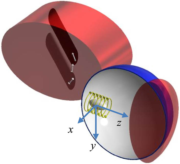
    Fig. 1. Layout of the Faraday-rotation measurement. The polarizations of the light passing above and below the beam are rotated oppositely.
    Layout of the Michelson-type interferometer. The polarizer only allows the transmission of the polarization-rotated light. The probe beam is amplified N1 times by a pair of lenses and then split into L1 and L2 by a beam splitter. L1 and L2 interfere with each other and the interference fringes are recorded by a CCD camera after being amplified N2 times by another amplification system.
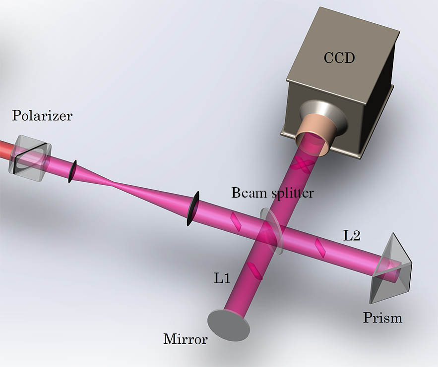
    Fig. 2. Layout of the Michelson-type interferometer. The polarizer only allows the transmission of the polarization-rotated light. The probe beam is amplified N1 times by a pair of lenses and then split into L1 and L2 by a beam splitter. L1 and L2 interfere with each other and the interference fringes are recorded by a CCD camera after being amplified N2 times by another amplification system.
    (a) Magnetic field distribution of the electron beam and (b) the polarization rotation angle of the probe laser using Eq. (1) in the y-z plane from PIC simulations. The distribution of the polarization rotation angle of a Gaussian magnetic field profile (c) without and (d) with considering the transit time of the probe light.
    Fig. 3. (a) Magnetic field distribution of the electron beam and (b) the polarization rotation angle of the probe laser using Eq. (1) in the y-z plane from PIC simulations. The distribution of the polarization rotation angle of a Gaussian magnetic field profile (c) without and (d) with considering the transit time of the probe light.
    Intensity distributions of (a) L2 from Eq. (7) and (b) L1 and L2 from Eq. (10) in the plane x-y-z′ with τpro=100 fs; the normalized integral intensity traces of L2 along the (c) y axis and (d) x axis; (e) the normalized integral intensity profile of the overlapping region along the x axis; (f) the normalized intensity of the retrieved interference fringes in the x axis.
    Fig. 4. Intensity distributions of (a) L2 from Eq. (7) and (b) L1 and L2 from Eq. (10) in the plane x-y-z with τpro=100fs; the normalized integral intensity traces of L2 along the (c) y axis and (d) x axis; (e) the normalized integral intensity profile of the overlapping region along the x axis; (f) the normalized intensity of the retrieved interference fringes in the x axis.
    Intensity distributions of (a) L2 from Eq. (7) and (b) L1 and L2 from Eq. (10) in the plane x-y-z′ with τpro=250 fs; the normalized integral intensity traces of L2 along the (c) y axis and (d) x axis; (e) the normalized integral intensity profile of the overlapping region along the x axis; (f) the normalized intensity of the interference fringes in the x axis.
    Fig. 5. Intensity distributions of (a) L2 from Eq. (7) and (b) L1 and L2 from Eq. (10) in the plane x-y-z with τpro=250fs; the normalized integral intensity traces of L2 along the (c) y axis and (d) x axis; (e) the normalized integral intensity profile of the overlapping region along the x axis; (f) the normalized intensity of the interference fringes in the x axis.
    (a) Interference fringe interval vs. the incident angle between L1 and L2. (b) The resolution of the measurement as a function of N2 for different angles.
    Fig. 6. (a) Interference fringe interval vs. the incident angle between L1 and L2. (b) The resolution of the measurement as a function of N2 for different angles.
    Jiaqi Liu, Wentao Li, Jiansheng Liu, Wentao Wang, Rong Qi, Zhijun Zhang, Changhai Yu, Zhiyong Qin, Ming Fang, Ke Feng, Ying Wu, Cheng Wang, Ruxin Li. Faraday-rotation self-interference method for electron beam duration measurement in the laser wakefield accelerator[J]. Chinese Optics Letters, 2018, 16(7): 071202
    Download Citation