Electromagnetically induced transparency (EIT), a typical quantum interference effect, has been extensively investigated in coherent atomic gases. In recent years, it has been recognized that the plasmonic analog of atomic EIT, called plasmon-induced transparency (PIT), is a fruitful platform for the study of EIT-like propagation and interaction of plasmonic polaritons. Many proposals have been presented for realizing PIT in various metamaterials, which possess many unique characters, including the suppression of absorption of electromagnetic radiation, the reduction of propagation velocity, etc. Especially, nonlinear PIT metamaterials, obtained usually by embedding nonlinear elements into meta-atoms, can be used to acquire an enhanced Kerr effect resulted from the resonant coupling between radiation and the meta-atoms and to actively manipulate structural and dynamical properties of plasmonic metamaterials. In this article, we review recent research progress in nonlinear PIT metamaterials, and elucidate their interesting properties and promising applications. In particular, we give a detailed description on the propagation and interaction of nonlinear plasmonic polaritons in metamaterials via PIT, which are promising for chip-scale applications in information processing and transmission.
In the past three decades, much attention has been paid to the study of electromagnetically induced transparency (EIT) and related phenomena in various atomic systems[1,2]. Usually, EIT is observed in a three-state atomic gas with -type level configuration exposed to two (i.e. control and probe) laser fields, where two atomic ground states are linked to a common excited state. Due to the quantum interference effect induced by the control field, the absorption of the probe field is largely suppressed, even if it is tuned to a strong one-photon resonance. Furthermore, the dispersive property of the atomic medium is modified considerably, leading to significant reduction of the group velocity of the probe field. In addition, the Kerr nonlinearity of the atomic medium can also be greatly enhanced[3]. Based on these striking features, many applications of EIT have been realized, including lasing without inversion[4], slow light[5], precision measurement[6], quantum phase gates[7,8], quantum memory[9–13], etc. In addition, nonlinear extension of atomic EIT and their applications were also explored, including slow-light solitons and their storage and retrieval[14–18]. However, EIT in atomic gases often requires special and often cumbersome experimental conditions, such as large device size and ultracold temperature, which hampers compact chip-integrated applications working at room temperature.
In recent years, many efforts have been made on the classical analogue of EIT in various physical systems, such as coupled resonators[19,20], electric circuits[19–21], optomechanical devices[22,23], whispering-gallery-mode microresonators[24], and various metamaterials (see, e.g., Refs. [25–48]). Especially, the plasmonic analogue of EIT in metamaterials, called plasmon-induced transparency (PIT)[25–28], has attracted growing interest[29–48]. PIT is a typical destructive interference effect, resulted from the resonant coupling between the wideband bright mode and the narrowband dark mode in meta-atoms of plasmonic metamaterials[25], which is similar to that happening in three-level atomic gases working under the EIT condition. The most distinctive characteristics of PIT are the appearance of a large transparency window within the broadband absorption spectrum of the bright mode, along with extraordinarily steep dispersion and dramatic reduction of the group velocity of the relevant plasmonic polariton. PIT metamaterials can work in different regions of electromagnetic (EM) radiation frequency (including microwave[26], terahertz[27,31,34], infrared, and visible radiations[25,29,33]) and may be exploited to design chip-scale plasmonic devices, in which undesirable radiation damping can be largely suppressed. Such capabilities of the plasmonic metamaterials are very enticing, as they would enable a range of novel devices, such as low-loss metamaterials[25,27], highly sensitive sensors[30,31,35], optical buffers[32,34], -symmetric metasurfaces[38], ultrafast optical switches[34], and memorizers for the storage and retrieval of EM pulses[36,40,47].
However, most studies on plasmonic polaritons (i.e., EM waves coupled with charge density waves propagating along metal–dielectric interfaces) in PIT metamaterials were focused on the linear propagation regime. Because of highly resonant (and hence, dispersive) characters inherent in PIT metamaterials, linear plasmon polaritons inevitably undergo a significant deformation during propagation. Furthermore, due to the diffraction effect, which is significant for radiations with small transverse size or long propagation distance, a large distortion of linear plasmon polaritons is unavoidable. Therefore, it is necessary to seek the possibility to obtain a robust propagation of plasmonic polaritons. One way to solve this problem is to make PIT systems work in the nonlinear propagation regime. The nonlinear extension of metamaterials provides the possibility to find a wide variety of new nonlinear phenomena that are absent in conventional systems. The reason is that metamaterials can be designed and actively manipulated at will, and so, enhanced nonlinear response can be easily realized[49–63].
Sign up for Chinese Optics Letters TOC. Get the latest issue of Chinese Optics Letters delivered right to you!Sign up now
Note that, among various nonlinear metamaterials, PIT metamaterials possess many interesting features. First, the radiation damping of the bright mode in PIT meta-atoms can be greatly suppressed by the destruction interference effect induced by the dark mode. Second, the dispersion property of the system can be changed significantly, and hence, the propagating velocity of radiation can be largely reduced. Third, enhanced Kerr nonlinearity can be acquired through the resonant coupling between the bright and dark modes; especially, when nonlinear elements embedded into PIT meta-atoms have quadratic and cubic nonlinearities, the Kerr nonlinearity can be enhanced further via longwave–shortwave resonance. By exploiting the enhanced Kerr nonlinearity, plasmonic solitons and dromions (i.e., high-dimensional solitons with longwave and shortwave components) can be obtained, which have ultraslow propagation velocity and ultralow generation power. Fourth, due to the active character of PIT, plasmonic polaritons with orbital angular momentums (OAMs) can be obtained, which can be stored and retrieved with high efficiency and fidelity if some gain elements are inserted into the PIT meta-atoms and so on.
In this article, we present a brief introduction on recent theoretical developments of nonlinear plasmonic polaritons via PIT. We review several different physical schemes for realizing nonlinear PIT metamaterials. Interesting physical properties and promising applications of nonlinear PIT metamaterials are discussed, including the enhancement of Kerr nonlinearity, the realization of plasmonic solitons and dromions, the analogous atomic four-wave mixing (FWM) and vector plasmonic solitons, and the storage and retrieval of plasmonic polaritons with OAMs. Finally, perspectives on the further study of nonlinear plasmonic polaritons in metamaterials are given.
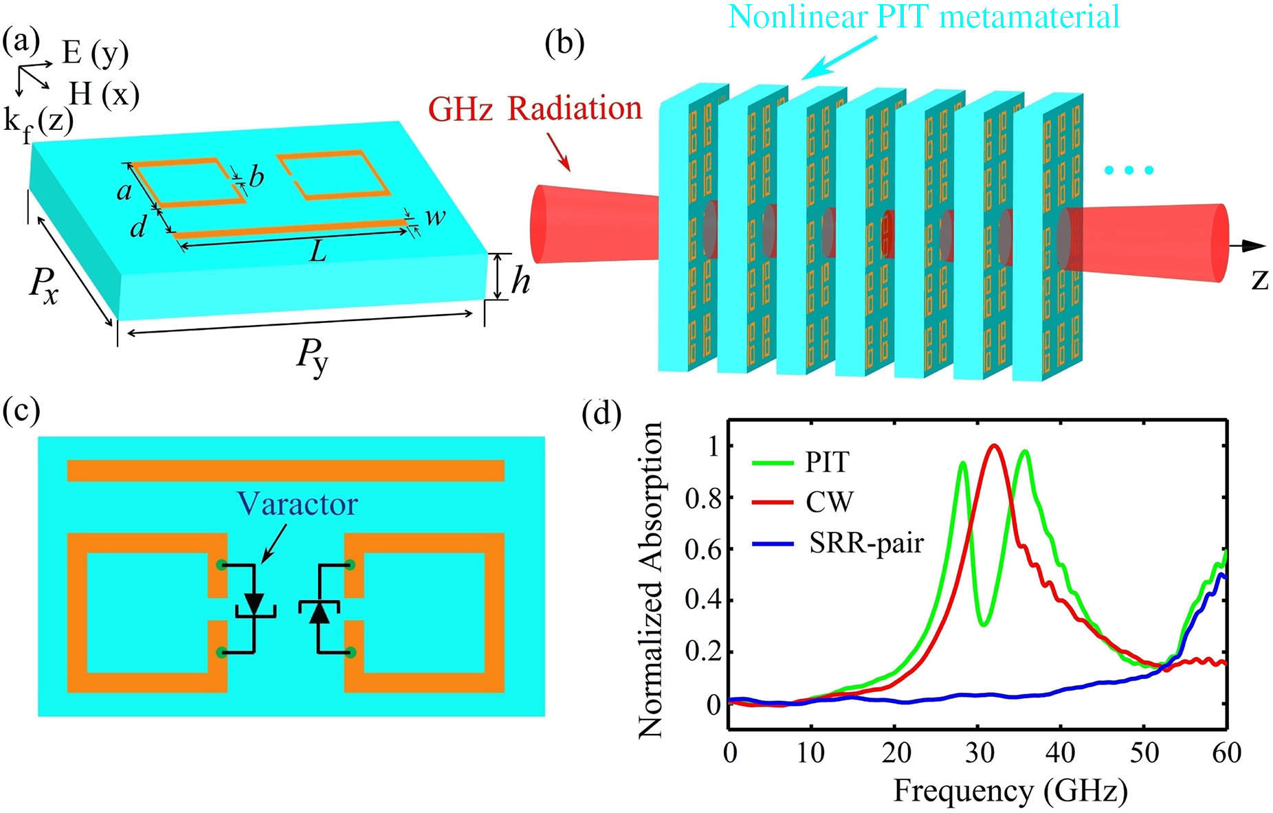
Ten years ago, Zhang et al.[25] proposed an array of meta-atoms that consist of one metal strip and two parallel metal strips to realize a PIT metamaterial. This pioneering work opened a new direction in plasmonic metamaterials and stimulated a series of researches on PIT[26–38,40–42,45,47,48]. In particular, Gu et al.[34] suggested that the meta-atom can be made by one cut wire (CW) and two splitting ring resonators (SRRs) [see Fig. 1(a)]. To get a PIT, an incident gigahertz (GHz) radiation is assumed to be collimated on the metamaterial array with the electric field parallel to the CW, as illustrated in Fig. 1(b)[64,65]. The normalized absorption spectra of the sole CW (red), SRR pair (blue), and the meta-atom of the linear PIT metamaterial (green) are shown in Fig. 1(d). The CW array shows a typical localized surface plasmon resonance, while the SRRs support an inductive–capacitive (LC) resonance at the same frequency. The CW is directly excited by the incident electric field along the CW, while the SRRs are weakly coupled to the incident field due to the perpendicular orientation of the field. The near-field coupling between the CW and SRRs excites the LC resonance in the SRRs, and hence, the CW and SRRs serve, respectively, as the bright and dark modes in such an excitation scheme, which leads to a dip at the center of the broad peak for the absorption spectrum.
Figure 1.(a) Schematic of the meta-atom (unit cell) in the linear PIT metamaterial, consisting of a metal CW and a pair of metal SRRs. Geometrical parameters of the meta-atom are , , , , , and . (b) SRR pair with a hyperabrupt tuning varactor mounted onto slits. (c) Possible experimental arrangement for the measurement of GHz radiation in the nonlinear PIT metamaterial. (d) Normalized absorption spectra of the CW (red), SRR pair (blue), and meta-atom of the linear PIT metamaterial (green). Adapted from Ref. [64].
The dynamics of the bright and dark modes in the meta-atom at the position are described by the Lorentz equations for two coupled oscillators[25,34,64,65]: where and are, respectively, amplitudes of the bright and dark modes, with and , respectively, their damping rates; and are, respectively, linear natural frequencies of the bright and dark modes (); parameter denotes the coupling strength between the CW and SRR pair; is the parameter indicating the coupling strength of the bright mode with the incident electric field .
Since an array of meta-atoms has been considered in the scheme presented [see Fig. 1(b)], and the distance between the meta-atoms is much less than the radiation wavelength, the system may be treated as an effective EM medium. The equation of motion for the electric field is governed by the Maxwell equation, with the electric-polarization intensity given by , where is the density of unit cells, is the unit charge, and is the optical susceptibility of the background material. In terms of the relation , the electric susceptibility can be obtained by the formula .
The normalized absorption spectra can be obtained directly by solving the coupled Maxwell–Lorentz (ML) Eqs. (1)–(3). We assumed the incident radiation has frequency , which is near . Thus, there is resonant interaction between the electric field and the oscillators and . Assuming the electric field to be proportional to ( is a constant), from Eqs. (1)–(3), one gets the linear dispersion relation
Here, and .
Shown in Figs. 2(a)–2(c) are, respectively, the normalized absorption spectrum versus frequency for separation , 0.24, and 0.02 mm, obtained by using the commercial finite difference time domain software package (CST Microwave Studio). One observes that a PIT window in the absorption spectrum opens, which means that the signal field can propagate in the system with negligible absorption. Such a phenomenon, similar to the EIT in atomic systems[1], is one of basic characters of PIT; furthermore, the transparency window becomes wider and deeper as is reduced. Figures 2(d)–2(f) show the absorption spectrum Im (the imaginary part of ) as a function of frequency. When plotting the figure, the damping rates and are used, which are nearly independent of , whereas decreases from 152.5 GHz at to 69 GHz at . One observes that the analytical result (the lower part of Fig. 2) fits well with the numerical one (the upper part of Fig. 2).
Figure 2.Numerical result of the normalized absorption spectrum of the linear PIT (Fig. 1) for (a) , (b) , and (c) , respectively. Analytical result given in (d), (e), and (f) is obtained from solving the model Eqs. (1) and (3) in the linear regime. Adapted from Ref. [64].
One can extend the model given above to work in a nonlinear regime through an insertion of a nonlinear varactor into the slits of the SRRs[64,65] [see Fig. 1(c)]. In this case, the dark oscillator in the meta-atom becomes an anharmonic one, i.e., Eq. (2) is replaced by the following nonlinear Lorentz equation[51,59]: where and are nonlinear coefficients, describing the nonlinear character of the varactor.
Now, the ML Eqs. (1), (3), and (5) are nonlinearly coupled ones. By inspecting their nonlinear feature, one can assume , . Here, , , and are, respectively, amplitudes of the longwave (rectification field or mean field), shortwave (fundamental wave), and second harmonic wave of the th oscillator, with () the wavenumber (frequency) of the fundamental wave; , , and are, respectively, amplitudes of the longwave, shortwave, and second harmonic wave of the electric field; () is the wavenumber (frequency) of the fundamental wave, and is a detuning. From the ML equations, using the rotating wave, and slowly varying envelope approximations (SVEAs), one can obtain a series of equations for the motion of and ().
The equations for and can be solved analytically by using the singular perturbation method of multiple scales[64,65]. Take the expansion , , , , , where is a dimensionless small parameter characterizing the amplitude of the incident electric field. All quantities on the right-hand side of the expansion are assumed as functions of the multi-scale variables , , , and . Substituting this expansion into the equations for and and comparing the expansion parameter of each power , one obtains a chain of linear but inhomogeneous equations, which can be solved order by order.
The first-order solution of the above expansion is the linear PIT one, given in the last subsection. However, in the present case, is an envelope function yet to be determined. At the second-order, a divergence-free condition requires , where is the group velocity of the (shortwave) envelope . With the above result, we proceed to the third order, where a divergence-free condition yields the equation
Here, (), is the coefficient describing linear absorption, is the coefficient describing group-velocity dispersion, , and are, respectively, the second-order and third-order nonlinear susceptibilities with the form
We observed that is proportional to the parameter , i.e., it is contributed by the quadratic nonlinearity in Eq. (5); is proportional to the parameters and , which means that it comes from the contributions by the quadratic and cubic nonlinearities in Eq. (5). Note that in Eq. (6) a longwave (rectification) field appears.
To get the equation for , one must go to the fourth-order approximation, which yields where is the phase velocity of the longwave field , defined by . The occurrence of the last term on the left-hand side of Eq. (9) is due to the plasmonic rectification contributed by the second-order nonlinearity in Eq. (5). Equations (6) and (9) are Davey–Stewartson equations[66], describing here high-dimensional nonlinear plasmonic polaritons in the system.
Shown in Figs. 3(a) and 3(b) are, respectively, curves of and as functions of the frequency detuning . One observes that is nearly real and has the order of magnitude ; the real part of the third-order susceptibility, Re(), has the order of magnitude . The physical reason for such large second- and third-order nonlinearities predicted here is the fact that the incident electric is resonant with the oscillators , , and the system works under the PIT condition. One also observes that the imaginary part of , which contributes a nonlinear absorption to the radiation field, is much less than the real part Re() when the system works in the PIT transparency window. Such suppression of the nonlinear absorption is also due to the PIT effect.
Figure 3.Nonlinear susceptibilities of the PIT metamaterial. (a) Real and imaginary parts of the third-order susceptibility [i.e., Re() and Im()] as functions of the frequency detuning . (b) Real and imaginary parts of the second-order susceptibility [i.e., Re() and Im()] as functions of . System parameters used are given in the text. Adapted from Ref. [65].
Interestingly, the third-order nonlinear susceptibility may be further enhanced using a longwave–shortwave resonance. For simplicity, consider the case that the transverse distribution of the radiation is large so that the diffraction effect is negligible. From Eq. (9), one obtains . Plugging this result into Eq. (6) yields which means that if (i.e., longwave–shortwave resonance), in addition to the PIT enhancement, the effective third-order nonlinear susceptibility can be further enhanced because of the drastic enhancement of . It was proved that such longwave–shortwave resonance may occur in the present nonlinear PIT system. For more detail see Ref. [65].
Illustrated in Fig. 4(a) is the denominator of as a function of and . The rectangle enclosed by purple dashed lines in the upper part of the figure illustrates the parameter region where . Consequently, the longwave–shortwave resonance can indeed happen in the system.
Figure 4.(a) of as a function of frequency detuning and the coupling coefficient . The rectangle enclosed by purple dashed lines shows the region where the longwave–shortwave resonance occurs (i.e., ). (b) Real part Re() (orange solid line) and imaginary part Im() (green dashed line) of the effective third-order nonlinear susceptibility as functions of frequency detuning for . Adapted from Ref. [65].
Figure 4(b) shows curves of the real part and the imaginary part of the effective third-order nonlinear susceptibility as functions of for . We observed that Re() [which is much larger than Im() near ] is enhanced by one order of magnitude (up to the value ), which is contributed by the longwave–shortwave resonance interaction[65].
Consider first the simple case where the transverse distribution of the radiation is large enough so that the diffraction effect of the system can be neglected. Then, Eq. (6) for is simplified to the nonlinear Schrödinger (NLS) equation, when returning to the original variables, where , , and .
Generally, Eq. (12) has complex coefficients, and hence, it is a Ginzburg–Landau equation. However, due to the PIT effect, the imaginary part of the complex coefficients can be made much smaller than their real part[65]. The electric field of the system corresponding to a single-soliton solution reads , with being the typical pulse length, being the absorption length, and , which describes a damped bright soliton traveling with velocity .
With the system parameters, the propagating velocity of the soliton is found to be . Thus, the plasmonic soliton found is a slow one similar to that found in an EIT atomic system. The peak power of the plasmonic soliton can be estimated by using Poynting’s vector integrated over the cross-section of the radiation in the transverse directions, given by , which means that to generate the soliton in the present system, a very low input power is needed. This is a drastical contrast to the case in conventional media, such as optical fibers, where picosecond or femtosecond laser pulses are needed to reach a very high peak power [usually at the order of several hundred kilowatts (kW)] to stimulate enough nonlinearity for the formation of solitons.
The stability of the plasmonic soliton was tested by using numerical simulation. Figure 5(a) shows the result of the radiation intensity of the soliton as a function of and . The solution is obtained by numerically solving Eq. (12) with the complex coefficients taken into account. One sees that the shape of the soliton undergoes no apparent deformation during propagation. The collision between two plasmonic solitons was also studied numerically, with the result shown in Fig. 5(b). One sees that both solitons can resume their original shapes after the collision, indicating that solitons in the PIT metamaterial are robust during interaction.
Figure 5.Propagation of the plasmonic soliton and the interaction between two plasmonic solitons. (a) The radiation intensity of the soliton as a function of and . (b) The collision between two solitons. Adapted from Ref. [64].
If the transverse distribution of the radiation is small, the diffraction effect of the system will play a significant role. In this case, it is possible to obtain high-dimensional nonlinear plasmon polaritons. Equations (6) and (9) are coupled ()-dimensional nonlinear equations, which include effects of dispersion, diffraction, and nonlinearity. For simplicity, first we assume that the dispersion length , diffraction length , and nonlinearity length have the same order of magnitude, which can be achieved by taking and . Second, by choosing realistic system parameters, the loss is small and can be safely taken as a perturbation. Then, Eqs. (6) and (9) turn out to be completely integrable and can be solved exactly by the use of inverse scattering transform, and various solutions of dromion [i.e. ()-dimensional solitons with longwave and shortwave components] can be obtained[65,66]. A single-dromion solution consists of a localized envelope (proportional to the shortwave envelope ) [Fig. 6(a)] and two plane solitons for the longwave component (proportional to the shortwave ) [Fig. 6(b)].
Figure 6.Plasmonic dromions and their collision. (a) [(b)] is the intensity profile of the shortwave (longwave ) as a function of and at . (c1), (c2), (c3), (c4) [(d1), (d2), (d3), (d4)] are intensity profiles of the shortwave (longwave ) during the interaction between two dromions, respectively, at . System parameters are given in the text. Adapted from Ref. [67].
Shown in Figs. 6(c1)–6(c4) [Figs. 6(d1)–6(d4)] are the numerical results for the evolution of the shortwave (longwave ) during the collision between two dromions. One sees that two initial dromions become four after the collision, which separate gradually and propagate almost stably, indicating that the collision between dromions is inelastic. With the system parameters, the average peak power of the plasmon dromion is , which corresponds to the average peak intensity . One sees that in the PIT metamaterial, extremely low generation power is needed for generating ()-dimensional spatiotemporal dromions.
Based on the idea of the classical analog of EIT, the atomic FWM can be classically analogous with the PIT metamaterial as well[67]. In contrast to the EIT and the analogous PIT, where a bright (radiative) mode and a dark (trapped) mode are required, the atomic FWM and its analogy require two bright and one dark modes.
We first review the atomic FWM in brief. The double--type four-level atomic system can be used to describe a resonant atomic FWM process, as schematically shown in Fig. 7(a). The first laser field (i.e., the control field tuned to the transition with the half-Rabi frequency ) and the second laser field (i.e., the probe field tuned to the transition with the Rabi frequency ) can adiabatically establish a large atomic coherence of the Raman transition, described by the off-diagonal density matrix element . The third laser field, i.e., the control field tuned to the transition with the Rabi frequency , can mix with the coherence to generate a fourth field with the Rabi frequency resonant with the transition. The dark state reads , exclusive of the excited states and , provided that . Under rotating-wave approximation (RWA) and SVEA, the Maxwell–Bloch (MB) equations of the system in the linear regime (two weak probe fields are applied) reduce to where with (), and is the light-atom coupling coefficient. One sees that and are two bright oscillators due to their direct coupling to the probe fields and , but is a dark oscillator because it has no direct coupling to any of the two probe fields. The linear dispersion relation is given by
Figure 7.(a) Double--type four-level atomic system with the atomic states () coupled with two probe fields (with Rabi frequency ) and two strong control fields (with Rabi frequency ) . , , and are, respectively, the one-, two-, and three-photon detunings. (b) as a function of for different . EIT transparency window is opened near the central frequency of the probe fields (i.e., at ). The blue solid curve is , which always has a large absorption peak at for arbitrary and . Adapted from Ref. [67].
As shown in Fig. 7(b), displays two branches, one is the EIT-mode, and the other is the non-EIT mode with large radiation loss. For details, see Refs. [68,69] and references therein.
The possible classical analogue of the above four-level atomic model by using a metamaterial is assumed to be an array [Fig. 8(a)] of meta-atoms [Fig. 8(b)], consisting of two CWs (indicated by “A” and “B”) and an SRR. The CW A and CW B are, respectively, positioned along the and directions, while the SRR is formed by a square ring with a gap at the center of each side. We assume that an incident GHz radiation [with ()] is collimated on the array of the meta-atoms, with polarization component () parallel to the CW A (CW B).
Figure 8.(a) Schematic of the plasmonic metamaterial for an analog to atomic FWM, which is an array of meta-atoms. (b) The meta-atom consists of two CWs (indicated by “A” and “B”) and an SRR. For generating nonlinear excitations, four hyperabrupt tuning varactors are mounted onto the slits of the SRR. (c) The numerical result (blue dashed lines) of the normalized absorption spectrum of the EM wave as a function of frequency by taking , (first panel), and (second panel). (d) The numerical result (blue dashed line) of normalized absorption spectrum for , . Red solid lines in (c) and (d) are corresponding analytical results. Details on the figure can be found in Ref. [67].
Shown in Figs. 8(c) and 8(d) is the result of the normalized absorption spectrum. The blue dashed lines in two panels of Fig. 8(c) denote for two sets of and , in which the surface current is cooperatively induced through the near-field coupling between the SRR and CWs, resulting in a maximum enhancement of the dark-oscillator resonance, and thus, the substantial suppression of the absorption of the incident radiation, acting like a typical PIT metamaterial we refer to as the “PIT mode”. Oppositely, the blue dashed line of Fig. 8(d) denotes , in which the surface current is suppressed due to an opposite excitation direction, leading to a complete suppression of the dark-oscillator resonance. As a result, the radiation absorption is significant (acting like a sole CW), and hence, no PIT behavior occurs, so we refer to it as the “non-PIT mode”. One can see that the absorption spectrum profile depends on the excitation condition, which is quite different from the PIT absorption spectrum considered before.
The dynamics of two bright oscillators (i.e., CW A and CW B) and dark oscillator (i.e., SRR) in the meta-atoms can be described by the coupled Lorentz equations[25,30,34,64], where are displacements from the equilibrium position of the bright oscillators () and the dark oscillator (), with and , respectively, the damping rate and the natural frequency of the th oscillator; () is the parameter describing the coupling between the CW A (CW B) and the -polarization (-polarization) component of the EM wave, and () is the parameter describing the coupling between the CW A (CW B) and SRR. The absorption spectrum of the system can be alternatively obtained by [or ], shown by the red solid lines. The coefficients in Eq. (15) are then determined by fitting the monochromatic solutions with the numerical results presented in Figs. 8(c) and 8(d) under the same input condition. If the two bright oscillators are not excited, one arrives at the “dark state” of the system, which can be excited if , equivalent to the one obtained in the four-level double--type atomic system. Obviously, the PIT mode shown in Fig. 8(c) corresponds to the case , where the minus symbol can be understood as a -phase difference, resulting in a cooperative coupling effect.
By assuming and , where and are slowly varying envelopes and is a small detuning, under RWA and SVEA one obtains the reduced ML equations with , , . One sees that Eq. (16) has a similar form to the atomic optical Bloch equation of Eq. (13). Consequently, each meta-atom in the metamaterial is analogous to a four-level double--type atom in atomic gas. The coupling between the CW A (CW B) and the SRR, described by (), is equivalent to the control field () driven by the atomic transition ()[67].
The propagation feature of a plasmonic polariton in the metamaterial can be obtained by assuming all quantities in Eq. (16) proportional to . It is easy to get the linear dispersion relation which has similar form as the atomic one in Eq. (14), where , with and (). As expected, the metamaterial system allows two normal modes with the linear dispersion relation, respectively, given by the PIT mode and the non-PIT mode . Shown in Fig. 9(a) are Im() (blue dashed line) and Re() (red solid line) for (first panel corresponds to ) and (second panel corresponds to ), respectively. One sees that displays a transparency window (called the PIT transparency window) near , analogous to the EIT transparency window in of the four-level double--type atomic system [red dashed line and green dashed-dot line in Fig. 9(b)]. The steep slope of indicates a normal dispersion and a slow group velocity of the plasmonic polariton. As the coupling strength between the CWs and the SRR gets larger (i.e., the separations and are reduced), the PIT transparency window becomes wider and deeper, and the slope of gets flatter. The opening of the PIT transparency window is attributed to the destructive interference between the two bright oscillators and the dark oscillator through cooperative near-field coupling. Shown in Fig. 9(b) are the imaginary (red solid line) and the real (blue dashed line) parts of , which is nearly independent of the coupling constant (). One sees that has a single, large absorption peak, and has an abnormal dispersion near , analogous to of the double--type atomic system [blue solid line in Fig. 9(b)].
Figure 9.(a) Linear dispersion relation of the mode (PIT mode). Im() (blue dashed line) and Re() (red solid line) are plotted as functions of for (first panel) and (second panel). (b) Linear dispersion relation of the mode (non-PIT mode) for arbitrary (). Adapted from Ref. [67].
As indicated above, the meta-atoms in the present metamaterial system are analogous to the four-level atoms with the double--type configuration, and hence, an analogous resonant FWM phenomenon for the plasmonic polaritons is possible. That is to say, if initially only one (e.g., ) polarization component of the radiation is injected into the metamaterial, a new (e.g., ) polarization component will be generated. It was shown that the ML equations admit the solution , . Here, [ is the group velocity of the normal mode ], and are functions of , and is the initial input of the radiation. When deriving the above expression, and are used, and the fast-decaying non-PIT mode is neglected. One sees that the - and -polarization components of the radiation have matched group velocity . The conversion efficiency of the FWM reads
Shown in Fig. 10 is the FWM conversion efficiency as a function of the dimensionless optical depth for (blue dashed line) and for (red solid line). When plotting this figure, we have set and in order for a better analogue to the atomic system. The influence of can be effectively reduced by introducing a gain dielectric into the gaps of the SRRs[70–72]. From the figure, we see that for the case of exact resonance (i.e., ) the FWM efficiency increases and rapidly saturates to 25% when the dimensionless optical depth (i.e., ), indicating a unidirectional energy transmission from to . For the case of far-off resonance (i.e., ), the FWM efficiency displays a damped oscillation in the interval , indicating a back-and-forth energy exchange between and ; eventually, the efficiency reaches the steady-state value of 25% when (see the inset). Interestingly, the value of the FWM conversion efficiency may reach at (i.e., ).
Figure 10.FWM conversion efficiency as a function of the dimensionless optical depth for (blue dashed line) and (red solid line). Inset: FWM conversion efficiency for optical depth up to 300 for . Adapted from Ref. [67].
Note that when deriving Eq. (16), the diffraction effect has been neglected, which is invalid for the plasmonic polaritons with small transverse size or long propagation distance; furthermore, because of the highly resonant (and hence, dispersive) character inherent in the PIT metamaterial, the linear plasmonic polaritons obtained above inevitably undergo significant distortion during propagation. Hence, it is necessary to seek the possibility of obtaining a robust propagation of the plasmonic polaritons, which can be realized by using a nonlinear metamaterial, with the nonlinear varactors mounted onto the gaps of the SRRs [see Fig. 8(b)]. Then, Eq. (15c) is replaced by where , are nonlinear coefficients introduced before. Due to the quadratic and cubic nonlinearities in Eq. (19), the input radiation field (with only a fundamental wave) will generate longwave (rectification) and second harmonic components, i.e., (), with and a detuning in wavenumber. The oscillations of the Lorentz oscillators in the meta-atoms have the form (), with .
In order to solve the ML equations of the system, the radiation field is assumed to be weakly nonlinear, so a standard method of multiple scales is applied, similar to that used in the last section. At the first-order, the solution for the shortwave field is obtained, given by and , where , and is a slowly varying envelope function to be determined in higher-order approximations. Note that the non-PIT (i.e., ) mode decays rapidly during propagation; as indicated before, we only considered the low-loss PIT (i.e., ) mode. The calculation proceeds on the higher-order approximation, then follows the procedures for seeking low-power plasmonic solitons and dromions of the PIT mode, similar to that given in the last section. For details, see Ref. [67].
Based on the analogous FWM process, one can acquire the vector character of plasmonic polaritons (i.e., two orthogonal polarizations of the EM wave), which has a large suppression of the radiation loss for the PIT mode. The explicit expression for the electric field in the system takes the form when and are taken as the soliton or dromion solutions described in the last section[67]. Note that, different from the scalar model[64,65] introduced above, the polarization of the EM field obtained here can be actively selected by adjusting the separation between the CWs and SRR [i.e., and in Fig. 8(b), and hence, the coupling constants and ], which can serve as a polarization selector for practical applications[73,74].
In recent experiments, an important technique for plasmonic memory with PIT meta-atoms was proposed by Nakanishi and Kitano[40,47]. The meta-atom considered in Ref. [40] consists of a metallic structure loaded with the two varactors on two arms [see Fig. 11(a)]. The varactor on the left (right) arm in the meta-atom has variable capacitance [] and can be actively manipulated by using a controlled EM field. The meta-atom can be well modeled as a resistor–inductor–capacitor (RLC) circuit with external excitation, as sketched in Fig. 11(b), where the circuit elements and are radiation resistances, is the capacitance between neighboring meta-atoms in the vertical direction, and is the inductance of each metallic arm. The electromotive voltage is induced by the incident signal field that is parallel to the arm.
Figure 11.(a) The meta-atom consisting of a metallic structure loaded with two varactors with capacitance [] on its left (right) arm. (b) Equivalent RLC circuit model of the meta-atom. The electromotive voltage is induced by the incident signal field that is parallel to the arm. and are radiation resistances, is the capacitance between neighboring meta-atoms in the vertical direction, and is the inductance of each metallic arm. (c) Possible experimental arrangement for measuring the propagation of the signal field and multi-mode polarition memory in the PIT metamaterial. The signal (control) field is incident along the () direction. Adapted from Ref. [75].
The problem of EM-wave memory in a plasmonic metamaterial was first investigated theoretically in Ref. [75], where an array of meta-atoms is used, with the meta-atoms the same as that proposed in Refs. [36,47] [see Fig. 11(c)]. By such a system, it is possible to get ()-dimensional, multi-mode EM waves with OAMs, which have very slow propagation velocity and may be stored and retrieved through the switching-off and switching-on of the control field[75], as described below.
Assume that incident signal field is incident in the direction with the polarization direction along the axis (i.e., collimated on a metamaterial array with the electric field parallel to the arm of meta-atom unit cells), and a control field (continuous wave) is incident along the direction, as shown in Fig. 11(c). Both the signal and control fields are EM waves with frequencies at orders of GHz. If assuming the capacitance modulation of the varactors by the control field is small, and has the form (), with the modulation frequency and a phase constant, then one obtains the equations of motion for : where [ () is the electric charge at the varactor on the left (right) arm], , , and the electromotive voltage is induced by the incident signal field with electric field , with the height of the meta-atom unit cell. One sees that, similar to the traditional PIT system[25], () acts as a bright (dark) oscillatory mode with the resonant frequency (), which couples (does not couple) to the external field . One can also see that the parameters and are equivalent radiation resistances of the bright and dark oscillatory modes. In addition, one has , because the radiation from the bright oscillatory mode is much greater than that from the dark oscillatory mode.
Assuming the signal field has the form , here, and is the refractive index of the background material, where one has and . Under RWA, Eq. (21) reduces to where , is the parameter characterizing the coupling strength between the bright oscillatory mode in the meta-atom and the signal field, [] is the reduced damping rate of the bright (dark) oscillatory mode, and are quantities representing detunings, and is the “Rabi frequency” of the control field characterizing the coupling strength between the bright mode and the dark mode, which can be changed by adjusting the control field. Expecting no confusion in the reader, the primes will be omitted in the following calculation.
The equation of motion for can be obtained by the Maxwell Eq. (3), which under SVEA reduces to where and .
To investigate the propagation and memory of EM waves with OAMs, the signal-field envelope can be expanded into the form where and are radial and azimuthal coordinates in the frame of a cylindrical coordinate system, are expansion coefficients, are the Laguerre–Gaussian modes with
Profiles of the modes show concentric rings, the number of which is determined by the mode index . The mode index is contained in the azimuthal phase term , which gives rise to intertwined helical wave-fronts, i.e., the surfaces of equal phase. The handedness of these helixes is determined by the sign of . Since , here, , modes carry OAMs along the direction and are usable for information processing with large capacity[76,77].
It is convenient to express the bright and dark oscillatory modes in the same basis as used for the signal field, i.e., we take the following expansions: where and are expansion coefficients. Substituting Eqs. (24) and (26) into the MB Eqs. (22) and (23), multiplying , and making the integration for and , the MB equations for the expansion coefficients , , and can be obtained[75].
For obtaining a deeper insight, a simple case was considered, in which the control field depends on time, i.e., . If the control field is changed adiabatically, and can be neglected, from the above equations, one can obtain the equation for plasmonic polariton, where , with and . There are two interesting features for . First, it is a combination (hybridization) between the EM signal field and the mode oscillation . Second, it is always shape-preserved during propagation, with the propagation velocity , which can become zero through manipulating . Such polariton carries OAMs because the complete combination function including the transverse modes is given by , and they predict possible storage and retrieval of the multi-mode EM waves.
To get more understanding on the storage and retrieval of the EM waves in the system, it is necessary to make further numerical simulations by removing the assumption of and making the simulations directly based on the MB Eqs. (22) and (23). Shown in Fig. 12 is the result of the intensity distributions of the signal field with the transversal LG modes in the - plane before and after storage for and . Figure 12(a) gives the intensity patterns for the superposition of a set of LG modes [] at the time , , , and , respectively. Figures 12(b) and 12(c) give similar intensity patterns as in Fig. 12(a), but, respectively, for the superposed LG modes [] and []. In the figure, the first column (for ) is the patterns before storage, the second and third columns (for and ) are the patterns during storage, and the fourth column (for ) is the patterns after storage. The fifth column shows the phase distribution of the input LG modes.
Figure 12.The storage and retrieval of the ()-dimensional signal field. (a) The intensity patterns for the superposed LG modes [] in the x-y plane, respectively, at the time , , , and . (b) The same as (a) but for the superposed LG modes []. (c) The same as (a) but for the superposed LG modes []. The first column is the patterns before storage, the second and third columns are the patterns during storage, and the fourth column is the patterns after storage. The fifth column shows the phase distribution of the input LG modes. Adapted from Ref. [75].
The above result shows that the ()-dimensional multi-mode EM waves with OAMs can indeed be stored and retrieved by actively manipulating the control field. In particular, the phase distribution of the LG modes, which carry OAM information, can also be stored and recovered again. To describe the quality of the PIT-based memory quantitatively, similar to Ref. [11], we define the memory efficiency for a given storage period. Figure 13 shows as a function of for the storage period . The red solid, blue dashed, green dotted, and purple dashed–dotted curves in the figure are for taking , , 0, and , respectively. From the figure, we can obtain the following conclusions. (i) For all , as increases, the memory efficiency first has a fast growth, then arrives at a peak value, and finally decreases slowly. (ii) The smaller the damping rate , the larger the peak value of . For instance, can reach 94% at cm for . The existence of is mainly due to ohmic loss, which, however, can be suppressed by introducing gain elements into the dark-mode oscillator. For instance, one can inset tunnel (Esaki) diodes into the two metallic arms of the meta-atom. The tunnel diodes have negative resistance[57], and hence, may provide gain to the PIT metamaterial. The method using tunnel diodes to compensate the ohmic loss in metals has been recognized as a promising technique, particularly in the microwave regime. In this way, one can make be very small and even take a negative value.
Figure 13.PIT-based memory efficiency as a function of propagation distance and for storage period . Red solid, blue dashed, green dotted, and purple dashed–dotted curves are for , taking , , 0, and , respectively. Adapted from Ref. [75].
In this article, several schemes for realizing nonlinear effects via PIT in plasmonic metamaterials have been briefly reviewed. Important properties and potential applications of these schemes have been discussed. Especially, the creation and propagation of nonlinear plasmonic polaritons (i.e., solitons, dromions, and vector solitons) based on PIT have been described in detail. The results obtained in these schemes are not only interesting for fundamental physics research but also promising for designing novel chip-scale nonlinear plasmonic devices that may be actively manipulated at very low radiation power.
Although in recent years much attention has been paid to various nonlinear metamaterials[59,60], and the study of nonlinear PIT has also attracted growing interest, further theoretical extension to the optical-frequency domain is still needed. On the other hand, it demands to develop experimental techniques for observing the nonlinear phenomena predicted by theory. Based on PIT, it is hopeful to fabricate novel low-loss metamaterials, highly sensitive sensors, optical buffers, ultrafast optical switches, memory devices, etc. Furthermore, for the research of linear and nonlinear PIT, there are yet many other research topics deserving of pursuit or exploration in depth; some of them are suggested in the following.
One of the topics is the study of surface polaritons (SPs) when multi-level quantum emitters are doped at the interface between a dielectric and a metamaterial[78–86]. In recent years, SP has become an active research topic in nanoplasmonics[78], involving all-optical control of SPs at subwavelength scales and various quantum optical applications. However, due to the inevitable ohmic loss in metals, the propagation distance of SPs is severely limited, hindering further progress towards practical nanoplasmonic devices. As a technique to solve this problem, one can introduce gain elements doped in the dielectric to compensate for the ohmic loss in metal. On the other hand, quantum emitters combined with PIT meta-atoms can be used to obtain new plasmonic metamaterials that may have useful functionalities for practical applications.
Another possible topic is the storage and retrieval of nonlinear polaritons in plasmonic metamaterials. Due to their rich physics and important applications in information processing, in recent years, light memory in atomic systems has attracted much attention in both theory and experiments[9–13]. In metamaterial science, a challenging problem is how to obtain radiation pulses that are stable during propagation and can be stored and retrieved with high efficiency and fidelity. Due to the balance between dispersion, diffraction, and Kerr nonlinearity, plasmonic solitons are robust, and hence, their storage and retrieval are more desirable than those of linear plasmonic polaritons[75]. Thus, it will be interesting if one can realize the memory of plasmonic solitons via PIT.
Lastly, the theoretical method developed for investigating the PIT in nonlinear metamaterials described in this review may be generalized to the study of all-dielectric analogue of EIT, a brand new research direction proposed quite recently[46,87]. We anticipate that nonlinear PIT, including but not limited to nonlinear effects, will attract tremendous research interests and find more practical applications in the near future.