Jin-Long SU, Fei HU, Yan TIAN, Tao ZHENG, Yan HU. Millimeter wave emissivity measurement of military coating materials[J]. Journal of Infrared and Millimeter Waves, 2021, 40(6): 761
Copy Citation Text
Materials samples of some common military coating including radar absorbing coating, high emission infrared coating, radar absorbing and high emission infrared compatible coating, radar absorbing and low emission infrared compatible coating, and aviation anticorrosive coating are prepared and their emissivity at different observation angles in Ka band is measured in this paper. An improved measurement scheme based on voltage method is proposed and used for the measurement experiments, The measurement scheme can eliminate the errors caused by antenna sidelobe and thickness difference between sample and reference bodies. In addition, the main sources of measurement uncertainty are analyzed and discussed.
Millimeter-wave (MMW)is between the microwave and terahertz wave in the electromagnetic spectrum,and covers the frequency ranges of 30∼300 GHz[1]. Passive millimeter-wave (PMMW)imager obtains the images with good resolution through collecting radiation from scenes in MMW band. PMMW imager is widely used in remote sensing[2-4],security checking[5-7],target detection[8-10] and medical applications[11-12]. Different from radar,passive imaging technology can image the target without inadvertently giving away the sensor location because that it does not transmit power actively. In addition,MMW sensor has the ability to image through both natural and manmade obscurants,such as smoke,fog,light rain,clothing,brownout conditions,and sandstorms. Due to these advantages,recently,the feasibility of using MMW radiometer to detect military targets has been discussed. Some researchers have carried out detection experiments on vehicles,ships and other targets by PMMW sensors[13-17]. In addition,Liu et al. did super simplest evaluation about the possibility of using radiometer for detecting objects with full radar absorption coating[18].They believed that compared with cold sky,the stealth aircraft is a “hot source” in PMMW images.
Thermal radiation is emitted by any object with a temperature higher than 0 K. Emissivity is a physical quantity that defines the ability in which an object emits electromagnetic radiation. Accurate knowledge of surface emissivity is essential in diverse fields such as target radiation characteristic evaluating and passive image simulating and modeling. As the same with infrared emissivity,the MMW emissivity is defined as the ratio of radiation from a material to the radiation from an ideal blackbody at the same temperature. The MMW emissivity of material is strongly dependent on wavelength,direction,observation polarization state,and so forth. Identifying material radiation capability is the foundation of target detection applications,and it is helpful for detection distance estimation and sensor design. Therefore,emissivity measurement of target samples in millimeter-wave band is of great significance.
Recently,several methods have been applied to MMW emissivity measurement. Initially,Miao et al. derived the emissivity of the coating by measuring the electromagnetic parameters of the coating materials[19]. In the works of Cheng et al.,the MMW emissivity of radar stealth coating and radar infrared compatible stealth coating at Ka band is measured by radiometer [20]. The measurements in his experiments are carried out outdoors so as to make the environment radiation reflected by the target stable and relatively low. The brightness temperature of the target scene,the physical temperature of the target surface and the radiation illuminates on the target surface comes from the cold sky are measured respectively,then the emissivity can be calculated by these results. Unfortunately,the comparison with the theoretical results shows that the accuracy of the measurement is unsatisfactory. Amali et al. conducted the emissivity measurement of human skin in W bands [12]. They built an indoor measurement platform and a low temperature radiation environment by absorbing foam and liquid nitrogen. This design makes the ambient radiation more uniform and stable. However,since it is difficult to cover the whole antenna pattern with palms or other measuring targets,errors may be introduced into the results.
All the above methods fail to consider the problem of antenna pattern overflowing target. In this regard,we have proposed an improved method named voltage method in the previous works. In this method,the emissivity is obtained by measuring blackbody reference,metal plate and the target sample of the same size at the same geometry by radiometer. The results of measurement experiment confirmed the effectiveness of the method[21]. On the promise that the radiometer is a linear system,the other advantage of this method is that the measured value can be obtained directly from the output voltage of the radiometer instead of the brightness temperature,thus,the tedious calibration for radiometer is avoided. It is a little pity that the thickness differences will lead to the differences of the effective radiation area of each sample material,and the edge scattering will also be different.
In this paper,the emissivities of radar absorbing coating,high emission infrared coating,radar absorbing and high emission infrared compatible coating,radar absorbing and low emission infrared compatible coating,and aviation anticorrosive coating are measured from multiple angles in Ka band. In the experiments,in order to avoid the measurement errors caused by the thickness difference,an improved measurement scheme is proposed,and the effectiveness is verified by experiments. Furthermore,the measurement uncertainty under different measurement conditions is analyzed.
1 Measurement method
Blackbody is an idealized body that represents a prefect absorber and a perfect radiator [1]. The emissivity of an opaque sample is lower than 1,which means that the observed radiance contains radiance not only emitted from the surface of the sample but also from the surrounding environment reflected by the sample surface. The apparent temperature TAP can be expressed mathematically as
,
where,Tbgrepresents the radiation temperature from the background,e is the directional emissivity. ρ is the hemispherical-directional reflectance of the surface,which equals to (1-e)at the condition of thermal equilibrium. For smooth surface,ρ equals the specular reflectance.
Radiometer receives the radiation from the observation scene through antenna. Different from optical devices,the antenna has relatively wide beam distribution in MMW band. Under the condition of far-field measurement,a large-scale target sample is needed to cover the whole antenna main beam. Then the antenna temperature TA can be written as
,
where,Fn(θ,φ)represents the pattern of radiometer antenna. Equation 2 is valid when the sensor is reasonably close to the sample,so that atmospheric extinction and emission in the relevant wavelength ranging along the line of slight are negligible.
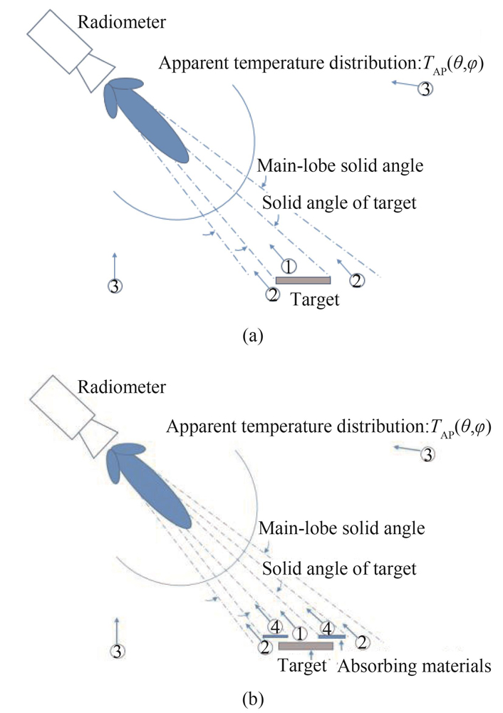
However,it is difficult to prepare large size samples so as to ensure that the whole pattern can be covered in the emissivity measurement. Actually,it is almost impossible for a sample to completely cover the sidelobe. As shown in Fig. 1 (a),the integral in Eq. 2 can be divided into three parts for opaque sample. ① represents the contribution of the target coverage area to the pattern. ② represents the contribution of radiation from the non-target region received by main lobe. ③ represents the contribution of radiation from the remaining directions received by side lobe.
Figure 1.Radiation contribution of each part (a) direct measurement, (b) measurement with measured window
In voltage method,metal plate and high-performance absorbing material are used as reference bodies. The target samples and reference bodies with the same size have been measured respectively at the same temperature,by the same detector and under the same observation geometry. The antenna measured temperature for the target and reference bodies and can be expressed as
, ,.
In MMW band,the emissivity of the metal plate can be considered as 0,and high-performance absorbing material can be considered as Eq.1. Connecting Eq. 1 and Eqs. 3-5,and when the physical temperature of the reference body and the target sample surface is equal,e can be solved as
,
For linear systems,Eq. 6 can be rewritten as
,
where,V is the output voltage value of radiometer,and can be converted into brightness temperature value by it calibration. The premise of the voltage method is that the metal reference body has the same scattering characteristics as the sample or the ambient radiation incident on the sample and the reference is diffuse in both directions.
When there is thickness difference between the target sample and the reference bodies,the measurement may introduce some errors due to the differences of the projection area of each measurement object in the measurement of bevel angles. The errors are related to the absolute value of thickness differences,the size of the samples and the observation angles. The bigger thickness differences,the smaller size or the larger angles will make the error larger.
This paper presents a scheme to avoid the error due to thickness differences. The diagram of the measurement scheme is shown in Fig. 1 (b). An area enclosed by absorbing material named measuring window is used to place the sample to be measured. The edges of the sample will be covered by absorbing material when the size of sample is larger than the size of the window. Therefore,the effective radiation area of the material samples and the reference bodies is the same in the measurement.
As shown in Fig. 1 (b),if a measuring window is used in measurement experiments,the antenna measured temperature for material sample and the reference samples can be respectively expressed as
,,,
where,TAPam is the apparent temperature of absorbing material around the measuring window. Ω1 is the solid angle occupied by the measuring window and the Ω2 is the solid angle occupied by the absorbing material. Connecting Eqs. 8-10,then
.
Connect Eq.1 and Eq.11,emissivity e can be calculated using the following equation:
.
For linear systems,Eq. 12 can also be written as Eq. 7. From the above mathematical process,it can be seen that the improved voltage method with measuring window can eliminate the influence of material edge very well.
2 Experiments
In this paper,the emissivity of common military coating materials is measured in Ka band. The pictures of these material samples in experiments are shown in Fig. 2. The materials numbered 1 to 3 are radar absorbing coating (RAC),high emissivity infrared coating (HEIC)and the combination of these two coatings respectively (RHC). The size of these samples is 180 mm×180 mm. The materials numbered 4 to 5 are the combination of low emissivity infrared coating and radar absorbing coating (RLC)and the aeronautical anticorrosive coating (AAC)with the size 500 mm×500 mm. The combined coating is achieved by painting the infrared coating on the surface of radar absorbing coating and then achieves stealth in both radar and infrared detection bands. These paintcoats are designed and manufactured by China North Industries Group Corporation (CNIGC). The main performance parameters are shown in Table 1.
Figure 2.Military coating material samples are measured in the experiments
A simple measurement prototype is built in our experiments. The prototype is mainly composed of a radiometer and a slideway which can adjust the observation angles. The radiometer works at the center frequency of 35 GHz with 400 MHz bandwidth. The measurement scenarios are shown in Fig. 3.
Figure 3.Measurement scenarios (a)the measurement based on voltage method, (b) the measurement based on improved voltage method.
The antenna of radiometer is about 2 m away from the target. In Fig. 3 (b),a measuring window with size 140 mm×140 mm is opened in an absorbing material foam and the samples are palced behind the window. The sample placement position can adjust the angles. Placing a sample on the platform allows measurement of the sample’s behavior as a function of angle. The radiometer is fixed on a bracket with adjustable height,so that the main beam of the antenna can be aligned with the center of the sample at any observation angles,so as to obtain higher measurement accuracy.
From Table 1,the RMS of surface amplitudes is smaller than one tenth wavelength in Ka bands,so the samples can be regarded as having smooth surface. The experiments are carried out outdoor,and cold sky is used as the background. A smooth metal plate and an absorbing foam are used as references in our experiments. The nominal absorptivity of the absorbing foam is greater than 0.995 and the directional reflectivity of the metal plate can be considered as 1 under any observation angles in the Ka band. In the measurement,the material target sample is fixed on sample holder firstly and the reference samples are moved in front of the radiometer in place of the sample. It ensur that the optical path and the background radiation as well as the responsivity of the radiometer remain unchanged during the three measurements. Then,the radiation of material sample,metal plate and blackbody is measured in turn and the measurement time approximates to 30 s. The same measurement is repeated 3 times,and 3 groups of emissivity results are obtained. The average of repeated measurement results is used as the final result.
Firstly,the radar absorbing paint is measured under several angles by voltage method with and without measuring window respectively. The results are shown in Fig. 4. From Fig. 4,we can see that the results of improved voltage method are higher than those of voltage method. With the increase of observation angle,the difference becomes larger. This is because in the voltage method,the thickness of the absorbing foam is larger than that of the material sample,which results in the lager projection area at the aperture of the antenna than the material sample. Then the denominator of Eq. 7 becomes lager,which makes the measurement results smaller. The results also prove the effectiveness of the improved method.
Figure 4.The comparison of measured results of radar absorbing coating
As can be seen from the results,the mean emissivity of the RAC at the observation angles is more than 0.88. The emissivity of HEIC is higher than 0.9 in 8~14 μm band,but its emissivity in the Ka band is very low. The mean emissivity and standard deviation of HEIC at the observation angles are 0.019 4 and 0.011 1 under vertical polarization,and are 0.027 4 and 0.013 8 under horizontal polarization. The measurement results showed high emissivity levels when the HEIC is painted on the surface of RAC. The mean emissivity and standard deviation of the RHC at the observation angles are 0.903 3 and 0.017 7 under vertical polarization,and are 0.923 6 and 0.016 7 under horizontal polarization.
In addition,the emissivity of the AAC and RLC is measured by improved voltage method. The emissivity of the LEIC is lower than 0.1 in 8~14 μm band. The observation angles are from 20° to 70°with the interval of 10°. The measured results of samples are plotted in Fig. 7.
Figure 7.Emissivity of aviation anticorrosive coating in Ka band
From the results,The mean emissivity and standard deviation of the aviation anticorrosive coating at the observation angles are 0.009 and 0.007 6 under vertical polarization,and are 0.007 3 and 0.005 under horizontal polarization. The results are similar to that of the high emissivity infrared coating. The main reason is that compared with infrared ray,the millimeter wave has better penetration ability,while the infrared coating and anticorrosive coating are very thin with only tens of microns in thickness.
The mean emissivity and standard deviation of the RLC at the observation angles are 0.922 7 and 0.030 8 under vertical polarization,and are 0.856 6 and 0.052 1 under horizontal polarization. In addition,an obvious phenomenon is that the emissivity under horizontal polarization decreases gradually under large observation angles.
3 Uncertainty
The main sources of the measurement uncertainty in our experiments include the temperature differences between the samples and the absorbing foam,the sensitivity of radiometer,the performance of the absorbing foam and the metal plate. Due to the low time cost,the reflected ambient radiation is assumed to remain constant within one measurement cycle. The uncertainty caused by the repeatability of the measurements is ignored.
The temperature of experiments environment is 290 K. The ambient radiation reflected by samples comes from cold sky. It is assumed that the ambient radiant brightness temperature is 150 K. The surface temperatures of the samples and the references are measured by probe thermometer and the difference is less than 0.5 K. The sensitivity of the radiometer is 0.6 K. The emissivity uncertainty of metal plate and blackbody is 0.005. For different emissivity values,the uncertainty of main components is given in Table 2.
From Table 2,the uncertainty of blackbody emissivity is the main measurement uncertainty source and the values are about 0.011 7,0.013 0 and 0.015 7 corresponding with emissivity values of 0.1,0.5 and 0.9 respectively. The corresponding total uncertainty is 0.013 3,0.016 0 and 0.021 1 respectively.
Ambient brightness temperature is a key quantity for analyzing the measurement uncertainty of the voltage method and the improved voltage method. Taking the experiment parameters as an example,the influence of ambient radiation which illuminates on the sample surface on the uncertainty of emissivity is shown in Fig. 9. When the ambient brightness temperature is close to the surface temperature of the sample,the measurement uncertainty will increase gradually. When the two temperatures are equal,this emissivity cannot be given by voltage method and improved voltage method. For the sample which the surface emissivity is bigger than 0.1,the relative uncertainty of the measurement will be less than 10% if the ambient brightness temperature is below 120 K or above 650 K when the sample is at room temperature (surface temperature equal to 290 K). When the surface emissivity is bigger than 0.5,the relative uncertainty will be less than 3% if the ambient brightness temperature is below 150 K or above 520 K and these values are 180 K and 450 K when the emissivity is more than 0.9. The results prove that the accurate emissivity value can be obtained by improved voltage method through selecting the illumination source. The cold sky and other cold or hot manmade radiation sources can be used as the illumination source for normal temperature measurements.
Figure 9.Variation of relative uncertainty with ambient brightness temperature (the surface temperature of sample is 290 K).
In this paper,the emissivity of the radar absorbing coating,high emissivity infrared coating,anticorrosive coating and the combination coatings at several observation angles in Ka band is measured by improved voltage method. The measurement method proposed in this paper can be used to measure the emissivity of the given area of a target by adjusting the size of the measurement window,and can be used to measure the emissivity of the skin at different positions of the human body as well as other material samples. The analysis of uncertainty can provide the basis for the selection of measurement conditions and the evaluation of measurement errors. The results of the measurement experiments can be used as a reference for the analysis of radiation characteristics of military materials.
References
[1] F T Ulaby, R K Moore, A K Fung. Microwave remote sensing: Active and passive Vol. I microwave remote sensing fundamentals and radiometry. Wesley(1981).
[16] X Shi, G W Lou, X G Li et al. Modelling and calculating of millimeter wave radiant temperature for armored target. J. Infrared Milli. Waves, 26, 43-46(2007).
[17] H L Lu, Y N Li, G N Song et al. Research on the passive detection technology using space-borne synthesis aperture microwave radiometers for the sea surface target. J. Infrared Milli. Waves, 38, 674-682(2019).
Jin-Long SU, Fei HU, Yan TIAN, Tao ZHENG, Yan HU. Millimeter wave emissivity measurement of military coating materials[J]. Journal of Infrared and Millimeter Waves, 2021, 40(6): 761