
Dipa Ghindani, Alireza R. Rashed, Humeyra Caglayan, "Unveiling spontaneous emission enhancement mechanisms in metal–insulator–metal nanocavities," Photonics Res. 9, 237 (2021)
- Photonics Research
- Vol. 9, Issue 2, 237 (2021)
Abstract
1. INTRODUCTION
Tailoring the emission property of an emitter is of great interest in terms of understanding the fundamental physics as well as the application prospects. In particular, the coherent interaction of an atom with the electromagnetic field is an ideal testbed to study many fundamental aspects of quantum mechanics [1]. From an application point of view, the enhancement of spontaneous emission (SE) is vital because it can enable highly efficient light-emitting devices, low-threshold lasers [2,3], and highly efficient single-photon sources [4,5]. The emission of an emitter can be enhanced by properly tailoring its photonic environment. The environment can enhance the emission either by (i) increasing the spontaneous emission rate (i.e., Purcell enhancement), (ii) increasing the excitation rate intensity, or (iii) modifying the radiation pattern [6–8]. Among these three factors, local excitation field intensity modifies the excitation rate, while the modification in the radiative decay channels of an emitter enhances the Purcell factor. There have been several studies reported on the SE enhancement of an emitter predominantly focusing on Purcell enhancement [9,10]. These studies mainly used a photonic crystal cavity [11,12], a waveguide, and metallic structures such as metal thin film [13], grating [14], nanoantennas [15,16], and nanoapertures [17]. In all these approaches, the photonic environment is tailored to achieve the fluorescence enhancement. An efficient modification in the photonic environment of an emitter can be achieved by integrating it into an optical cavity with a high-quality factor (Q-factor) and a low-mode profile. The photonic crystal (PC) cavity is an example of a cavity that supports high Q-factor resonance [11]. However, the minimum possible mode volume offered by the PC cavity is limited by the diffraction limit [18]. In addition, the integration of a narrowband emitter with a high Q-factor cavity resonance requires intensive nanofabrication and lacks scalability. On the other hand, plasmonic nanostructures offer a low-mode volume at the plasmon resonance frequency [19]. However, due to the metallic losses, they suffer from a low Q-factor. In addition, the integration process for plasmonics nanostructures with deposited emitters in large areas is limited by their fabrication complexity. This restricts the translation of this approach for integrated photonics.
Metal–insulator–metal (MIM) structures, which emerged in recent years as high Q-factor Fabry–Perot resonators, are highly versatile to modify the properties of an emitter [20]. The ability to confine the light into the subwavelength-sized dielectric spacer is a remarkable property of an MIM cavity that has been used to demonstrate many disruptive applications in a plethora of fields from super absorption to high-resolution spatial color filters [21–23]. Among the diverse applications, the spontaneous emission rate enhancement has recently attracted the attention of the scientific community [24,25]. The fabrication simplicity and reproducibility of MIM structures are the major advantages compared to plasmonic nanocavity and PC cavity based approaches.
Prayakarao
Sign up for Photonics Research TOC. Get the latest issue of Photonics Research delivered right to you!Sign up now
We performed systematic theoretical and experimental studies to investigate underlying mechanisms related to the observed enhanced SE rate in MIM cavities. In this work, we use a silver (Ag) based MIM cavity [Ag–polymethylmethacrylate (PMMA)–Ag] to enhance the spontaneous emission rate of LDS 798 dye molecules. We observed enhancement in the photoluminescence (PL) intensity along with a change in the fluorescent lifetime components. In the studied dye-integrated hybrid system, two main mechanisms play a role in the emission enhancement process: Purcell effect enhancement due to confinement of the electromagnetic field between the two metallic films and excitation rate enhancement due to the strong cavity mode. A simultaneous overlap of the absorption and emission spectra of LDS 798 dye molecules with the cavity resonance of the designed MIM nanocavity provides the opportunity to exploit both processes to enhance the emission of hybrid systems with the highest efficiency. We show the role of the excitation rate enhancement to achieve an intensified emission in such a design. We believe our approach to the design of dye-integrated hybrid MIM systems opens the way to realize more efficient, lithography-free, and low-cost advanced nanoscale devices.
2. RESULTS AND DISCUSSION
The schematic of the fabricated MIM cavity is shown in Fig. 1(a), where the thickness of top and bottom metallic layers is 35 and 150 nm, respectively. Ag has been used for the metal layers due to its excellent plasmonic property and low losses. We deposited Ag layers using an e-beam evaporator and confirmed each layer’s thickness using a profilometer. PMMA was spincoated as a dielectric layer and the thickness of the dielectric layer was varied to tune the cavity resonance. The thickness of the dielectric layer was optimized using numerical simulation (Lumerical FDTD Solutions) based on finite-difference time-domain (FDTD) method. In simulations, the periodic boundary conditions were applied in the
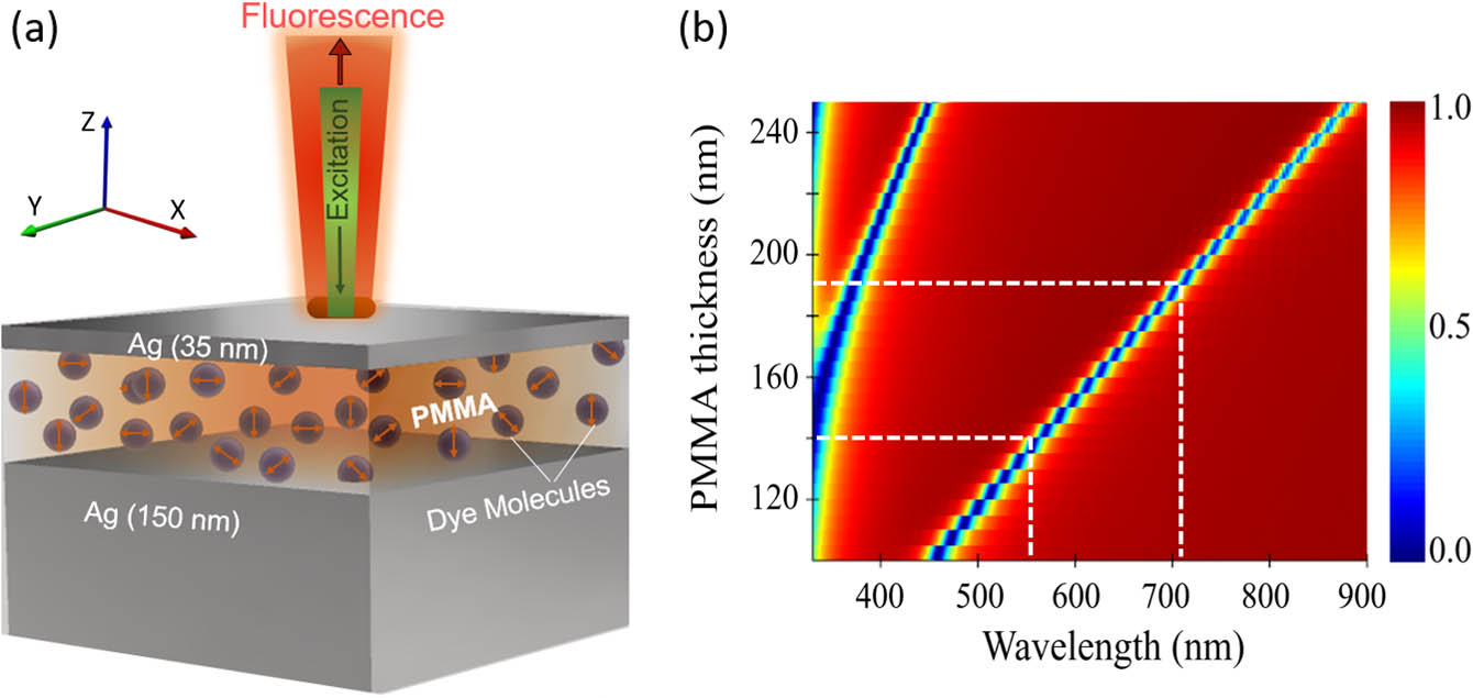
Figure 1.(a) Schematic of MIM (Ag–PMMA + LDS 798 dye–Ag) cavity. (b) Simulated reflection result for different thicknesses of dielectric layer. White dashed lines show resonance position of both cavities with thicknesses of 140 nm and 190 nm.
Figures 2(a) and 2(b) show the experimentally recorded absorption (black solid line) and emission spectra (red solid line) of the LDS 798 dye molecules, which confirms the absorption and emission peaks at 567 nm and 670 nm, respectively. The experimentally recorded reflection spectra for MIM-I and MIM-II are shown in Fig. 2 (blue solid line) and have good agreement with simulated reflectance results [Fig. 1(b)]. From Figs. 2(a) and 2(b), it is important to note that the resonance of the MIM-I cavity has a strong overlap with the absorption spectrum, whereas the resonance of the MIM-II cavity overlaps with the emission spectrum of the dye, but barely overlaps with the absorption spectrum.
![]()
Figure 2.Measured reflectance spectra of (a) MIM-I and (b) MIM-II cavities. The absorption and emission spectra of LDS 798 dye molecules are presented as black and red curves in both panels, respectively. The reflectance band of MIM-I cavity overlaps with the absorption peak and the emission tail of fluorescent dye, while the reflectance band of MIM-II overlaps with the emission of the dye and barely with absorption of dye.
To elucidate the effect of strong field confinement on the emission property of LDS 798, we experimentally recorded the intensity counts of the fluorescent dye molecules using PL measurement with a 532 nm excitation source. Figures 3(a) and 3(b) show PL counts for the dye integrated with MIM-I and MIM-II, respectively. From Fig. 3(a), it is evident that the incorporation of the dye molecules with the MIM-I cavity exhibits remarkable emission enhancement. We observed a 260-fold emission enhancement for the dye molecules integrated with MIM-I and only a 3-fold emission enhancement for MIM-II. In the case of MIM-I, the higher multifold enhancement can be attributed to an unequal combination of the Purcell effect enhancement and enhancement of the local excitation field, because the resonance band of the MIM-I structure overlaps strongly with the absorption spectrum and partially with the emission spectrum of the LDS 798 dye molecules. On the other hand, for MIM-II, excitation rate enhancement and Purcell factor enhancement work as two weak gateways to modify the spontaneous emission rate of the hybrid system.
![]()
Figure 3.Experimentally recorded steady-state PL spectra of LDS 798 dye molecules embedded in cavities (red solid lines): (a) MIM-I cavity and (b) MIM-II cavity. The recorded emission of embedded dye molecules in PMMA as a reference sample is shown as a black dotted line. Time-resolved fluorescence spectroscopy results of embedded dye molecules in the MIM cavities (red triangles): (c) MIM-I and (d) MIM-II. The recorded fluorescent lifetime of embedded dye in PMMA as a reference sample is shown as a black dotted line.
Furthermore, the transient PL decay traces of the dye molecules were measured through time-resolved fluorescence spectroscopy. The experimentally recorded transient decay dynamics is shown in Figs. 3(c) and 3(d). We have acquired the PL lifetime of the LDS 798 dye integrated with MIM cavities I and II, and embedded them in PMMA as a reference sample. We have used a bi-exponential function to fit kinetics of the reference and main samples, as shown in Table 1. The presence of LDS 798 molecules in a rigid matrix like PMMA hinders the large-amplitude motion and intermolecular beatings of the excited molecules. Moreover, in such a dense environment, the probability of the aggregation for the monomers of the dye increases. These effects can result in two fluorescent lifetime components rather than a single component, which is the case for the dissolved LDS dye molecules in low viscous solvents [26,27]. The applied bi-exponential function to fit PL kinetics of dye molecules in the reference sample (black circles) results in two characteristic lifetime components of
| Sample Lable | ||||
|---|---|---|---|---|
| LDS 798 | 1.144 | 41% | 2.408 | 59% |
| MIM-I | 1.074 | 75% | 3.691 | 25% |
| MIM-II | 0.990 | 33% | 2.404 | 67% |
Table 1. Time-Resolved Fluorescence Spectroscopy Results for the MIM-I and MIM-II Nanocavities and LDS 798 Dye Molecules Embedded in PMMA
The reduction in the fast decay component can be attributed to the emission rate enhancement due to the Purcell effect. However, the slower component increases due to leakage radiation from the MIM-I cavity. Since the cavity resonance of MIM-I (at 567 nm) is far from the emission peak [670 nm, Fig. 2(a) red solid line], the part of the emission that does not couple with the MIM-I cavity results in slow leakage field. This leakage occurs due to the thin metallic top layer (35 nm), which is unable to effectively confine the emission of the nonresonant dye molecules embedded inside the cavity in the off-resonant spectral region. In the case of MIM-II, the characteristic lifetime components are
Consider that the absorption of the metallic layers can influence the emission enhancement process of the excited dye molecules. Moreover, the occurrence of nonradiative quenching mechanisms such as nanosurface energy transfer (NSET) [28] and resonance energy transfer (RET) [29] between the dye molecules and probable roughness of the metallic films is possible. In addition, the resonance energy transfer between the monomers and multimers of the dye molecules is probable [30]. However, as the time-resolved fluorescence spectroscopy results for both nanocavities do not depict extremely short lifetime components, nonradiative loss channels evidently are not influential in the emission enhancement process. This is due to the fact that the evaporated metal layers are smooth enough and a small portion of the excited dye molecules are located in the vicinity of the metallic films. Therefore, in our case, the influence of the loss mechanisms on the spontaneous decay rate enhancement is negligible.
To unveil the underlying physics for multifold enhancement, we performed numerical simulations to calculate the electric field confined inside nanocavities. Figures 4(a) and 4(b) show the electric field contour plot of MIM nanocavities with a strong electric field confinement in the dielectric region (PMMA) at cavity resonance wavelengths; i.e., 567 nm and 710 nm, respectively. Thus, one can expect that the incorporation of dye molecules with the designed MIM cavities can lead to fluorescence enhancement.
![]()
Figure 4.Simulation results for the electric field contour plot in the two nanocavities: (a) MIM-I and (b) MIM-II. The insets in panels (a) and (b) show the schematics of the MIM-I and MIM-II designs, respectively. The Purcell factor calculation for the two cavities: (c) MIM-I and (d) MIM-II. The higher mode profile describes the lower Purcell factor of the MIM-II cavity with respect to that of MIM-I.
In this study, the resonance of the MIM-I cavity overlaps partially with emission spectrum while efficiently with the absorption band of the dye, as shown in Fig. 2(a), that results in an increase in fluorescence emission via two gateways: mainly by enhancing the local field intensity, which leads to a stronger population of the excited state, and slightly by increasing the spontaneous emission rate of emitter (i.e., the Purcell enhancement). Further, to emphasize our reasoning, we numerically calculated the Purcell factor of our integrated devices, as shown in Figs. 4(c) and 4(d) for the MIM-I and MIM-II cavities, respectively. For the Purcell factor calculations, we used Lumerical FDTD Solutions software, where a dipole source is used to emulate the photoexcited dye molecule. The dipole source is located in the middle of the dielectric layer of the MIM structure. The orientation of the dipole is varied from the
3. CONCLUSION
In conclusion, we have shown a fluorescence enhancement of LDS 798 dye molecules by integrating them with an MIM cavity. We unrevealed the mechanisms behind the emission enhancement process in the MIM nanocavities integrated with quantum emitters. This is performed by designing two different MIM cavities. The absorption spectrum of the dye overlaps efficiently with the resonance of MIM-I, but barely with the resonance of MIM-II. Our comprehensive study shows that the dye integrated with MIM-II shows only a 3-fold enhancement. On the other hand, the MIM cavity that is optimized to have a resonance peak overlapping with the absorption of the dye exhibits an exceptionally high enhancement of 260-fold in the photoluminescence intensity. This arises as a combination of the Purcell effect and the excitation rate enhancement. Hence, according to our findings, the observed remarkable high emission enhancement for quantum emitters embedded in MIM nanocavities is attributed mainly to the excitation rate enhancement rather than the Purcell enhancement.
The MIM-nanocavity-based approach can be used to engineer the emission properties of an emitter by using enhanced light–matter interactions that would potentially lead to the development of efficient light-emitting devices or an enhanced energy transfer. Because MIM nanocavities possess multiple cavity modes with a high quality factor, this creates an opportunity to overlap the absorption band of a quantum emitter with the mode at the lower wavelength of the spectrum, while the emission spectrum can be overlapped with the mode at the higher wavelength. As a result, one can achieve a higher spontaneous emission enhancement for the incorporated quantum emitter inside the nanocavity. Another approach might be to integrate the dye molecule with an MIM with metasurfaces. In this way, it is possible to develop highly efficient, multifunctional integrated photonic devices where emission properties can be actively or passively tuned by changing the polarization of incident light and geometrical parameters of the metasurface. Thus, we believe our findings allow the design of low-cost, effective nanophotonic devices with enhanced functionalities.
Acknowledgment
Acknowledgment. The authors acknowledge the support of the Academy of Finland’s Flagship Programme (PREIN) and The Finnish National Agency for Education through an EDUFI Fellowship for author Dipa Ghindani. The authors also thank Jussi Toppari and Gerit Groenhof for scientific discussions of the results.


Set citation alerts for the article
Please enter your email address

© Copyright 2018-2021 | Chinese Laser Press. All Rights Reserved 沪ICP备15018463号-20