• NUCLEAR TECHNIQUES
  • Vol. 46, Issue 2, 020603 (2023)
Ruirong HU1,2, Naxiu WANG1,*, Bo XU1, Hongxin ZHANG1..., Ling LI1, Yun CAO1 and Shifeng ZHU1|Show fewer author(s)
Author Affiliations
  • 1Shanghai Institute of Applied Physics, Chinese Academy of Sciences, Shanghai 201800, China
  • 2University of Chinese Academy of Sciences, Beijing 100049, China
  • show less
    DOI: 10.11889/j.0253-3219.2023.hjs.46.020603 Cite this Article
    Ruirong HU, Naxiu WANG, Bo XU, Hongxin ZHANG, Ling LI, Yun CAO, Shifeng ZHU. Application of pneumatic conveying in reactor neutron spectroscopy sample transport[J]. NUCLEAR TECHNIQUES, 2023, 46(2): 020603 Copy Citation Text show less
    System schematic diagram P1/P2: Pressure gas tube; P3: Sample transport tube; V1: Gas reversing valve; V2: Gas pressure reducing valve; V3: Gas valve; V4: Ball valve
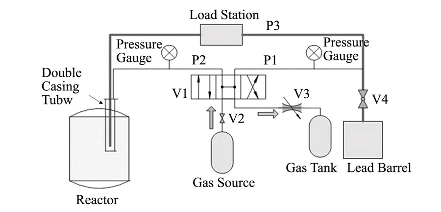
    Fig. 1. System schematic diagram P1/P2: Pressure gas tube; P3: Sample transport tube; V1: Gas reversing valve; V2: Gas pressure reducing valve; V3: Gas valve; V4: Ball valve
    Diagram of double casing tube
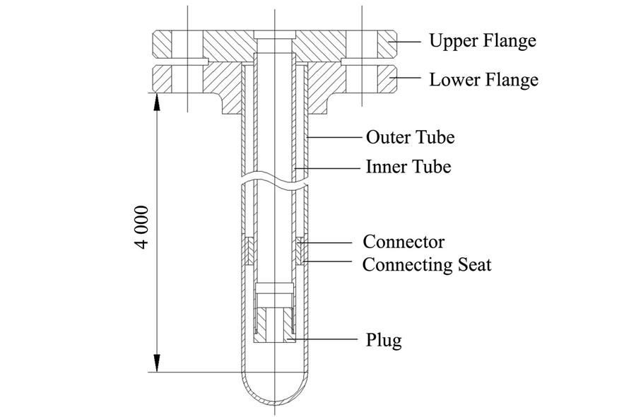
    Fig. 2. Diagram of double casing tube
    Schematic of the calculation model
    Fig. 3. Schematic of the calculation model
    Force on the sample in the pipe
    Fig. 4. Force on the sample in the pipe
    Varitions of sample speed over time in different gaps
    Fig. 5. Varitions of sample speed over time in different gaps
    Maximum pressure difference under different gaps
    Fig. 6. Maximum pressure difference under different gaps
    Diagram of principle prototype Enter the reactor: 1-Pneumatic conveying starting point, 2-Pneumatic conveying end; Out of the reactor: 2-Pneumatic conveying starting point, 3-Pneumatic conveying end
    Fig. 7. Diagram of principle prototype Enter the reactor: 1-Pneumatic conveying starting point, 2-Pneumatic conveying end; Out of the reactor: 2-Pneumatic conveying starting point, 3-Pneumatic conveying end
    Sensor installation (a) Sensor installation at the load station, (b) Sensor installation at the bottom of the double casing tube
    Fig. 8. Sensor installation (a) Sensor installation at the load station, (b) Sensor installation at the bottom of the double casing tube

    理论计算

    Theoretical

    calculations

    仿真分析

    Simulation

    analysis

    相对误差

    Relative

    error / %

    空气动力The

    resultant force

    of sample / N

    0.1950.1788.7
    Table 1. The simulation results and theoretical calculations are compared with the gas inlet flow rate of 6.7 m·s-1
    序号Serial number压损类型Gas-solid flow resistance type压损大小Size / Pa
    1加速压损Accelerated pressure loss373
    2摩擦压损Frictional pressure loss21 962
    3悬浮提升压损Suspension lift pressure loss530
    4局部压损Local pressure loss1 508
    5总压损Total pressure loss24 373
    Table 2. Gas-solid two-phase flow resistance

    序号

    Serial

    number

    气体流量

    Gas flow

    / L·min-1

    两相流压损

    Two-phase flow

    pressure loss / kPa

    样品速度实验值

    Experiment speed

    / m·s-1

    样品速度计算值

    Calculated speed

    / m·s-1

    理论计算与

    实验值偏差

    Deviation / %

    备注

    Remark

    1221.718.25.225.062.7

    进堆实验

    Reactor feeding experiment

    223819.25.425.98.5

    出堆实验

    Ex reactor experiment

    325019.96.416.562.4

    进堆实验

    Reactor feeding experiment

    432024.59.8710.274.6

    出堆实验

    Ex reactor experiment

    532824.710.1210.75.6

    出堆实验

    Ex reactor experiment

    Table 3. Sample transport experiment
    Ruirong HU, Naxiu WANG, Bo XU, Hongxin ZHANG, Ling LI, Yun CAO, Shifeng ZHU. Application of pneumatic conveying in reactor neutron spectroscopy sample transport[J]. NUCLEAR TECHNIQUES, 2023, 46(2): 020603
    Download Citation