
Zhicheng Jing, Guoyu Zhang, Zijian Wang, Wuhong Li, Chuanqiang Wang, Guojian Xu, Dongsa Chen, Wei Wang. Properties of Marine High-Strength Steel by High-Efficiency Laser-MAG Hybrid Welding[J]. Chinese Journal of Lasers, 2019, 46(8): 0802005
- Chinese Journal of Lasers
- Vol. 46, Issue 8, 0802005 (2019)
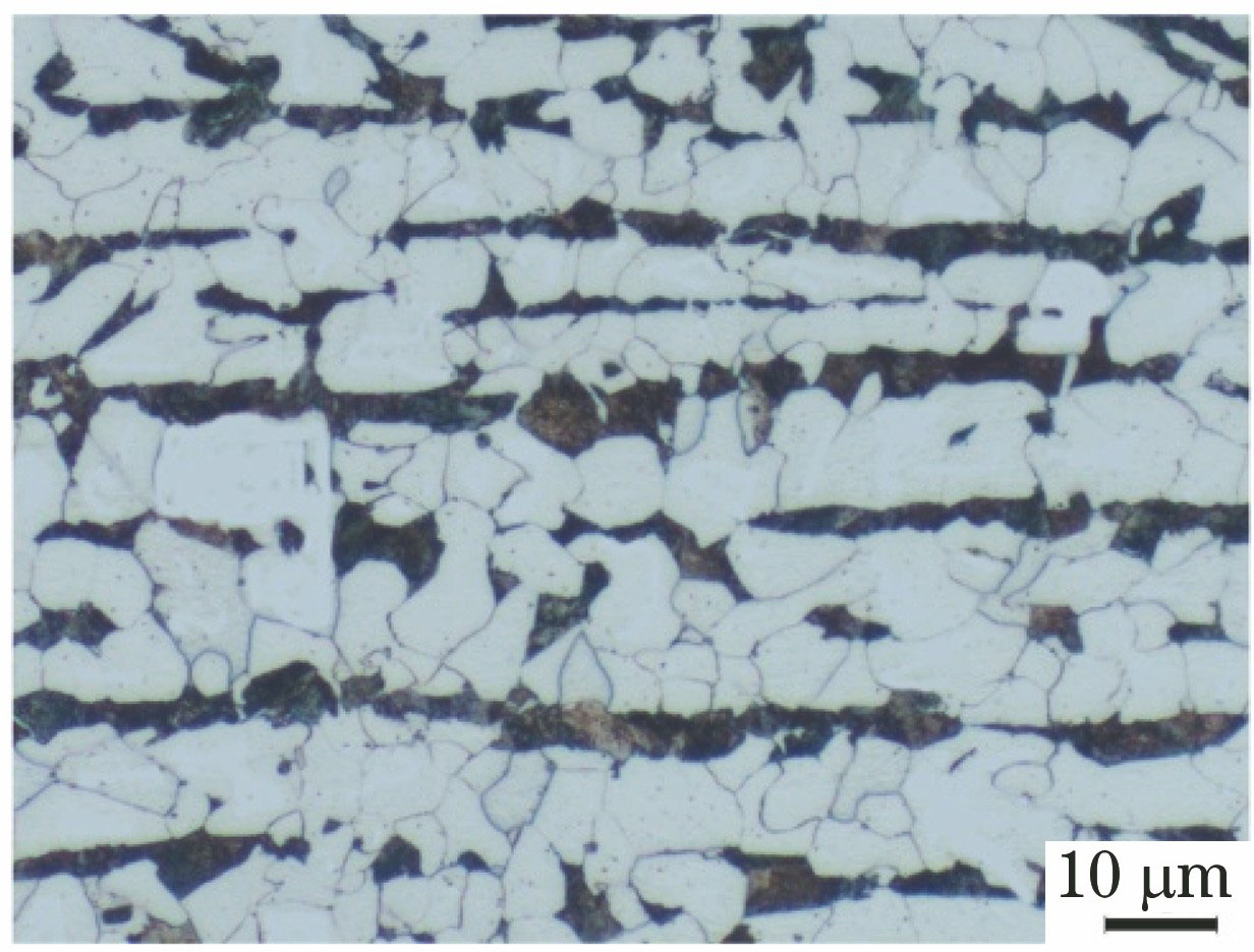
Fig. 1. Optical microstructure of BM
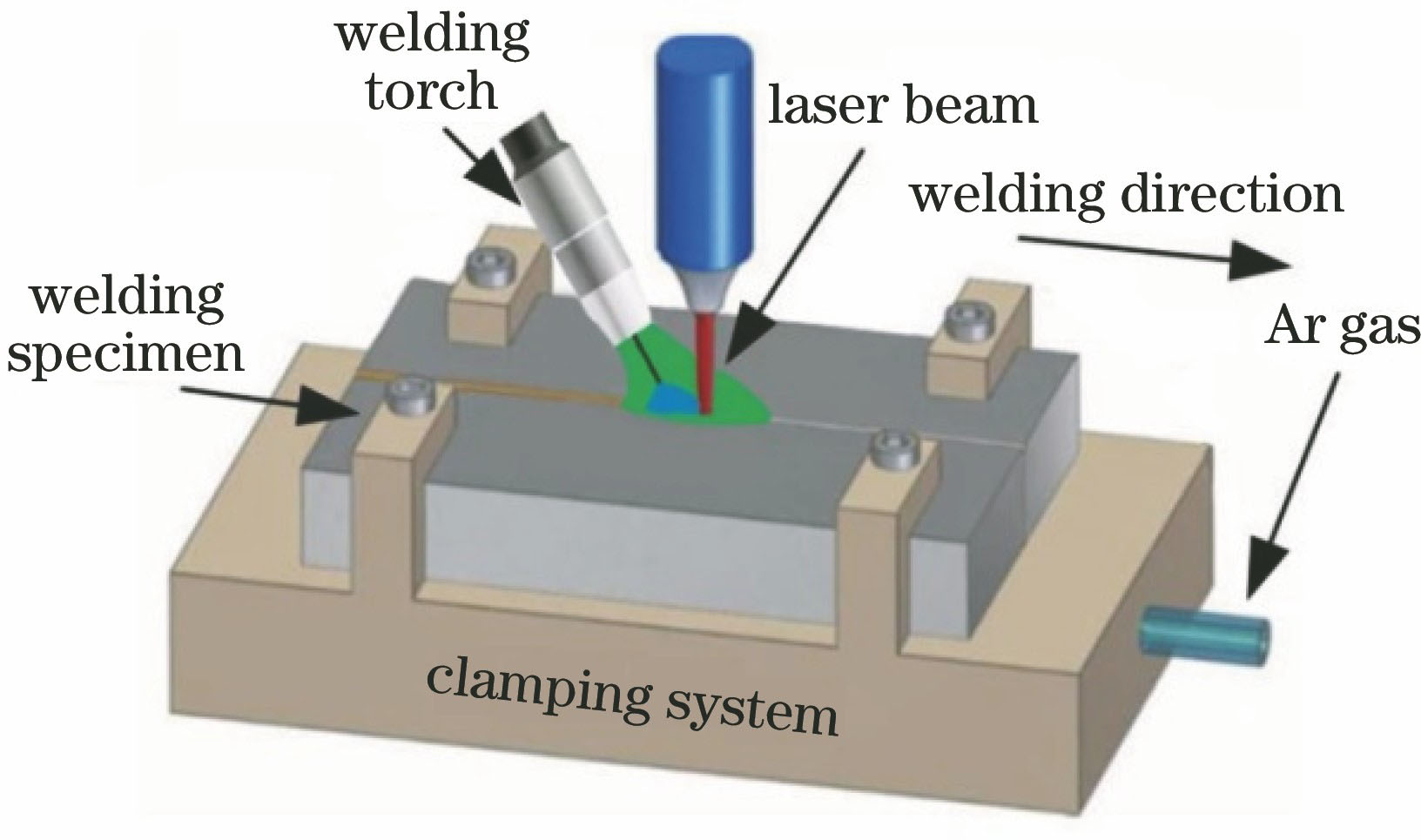
Fig. 2. Schematic of EH36 marine high-strength steel welding
Fig. 3. Morphologies of WM. (a) Front morphology; (b) back morphology; (c) cross-section of weld and zone division
Fig. 4. Microstructures of WM in arc action zone. (a) State of grain growth; (b) boundary of grains; (c) interior of grains; (d) V-shaped bonds
Fig. 5. Microstructures of WM in laser action zone. (a) State of grain growth; (b) microstructure
Fig. 6. Microstructures near fusion line of welded joint in arc action zone. (a) Fusion line; (b) coarse grain zone; (c) fine grain zone; (d) zone of incomplete phase change recrystallization
Fig. 7. Microhardness distribution curves at different positions of welded joint
Fig. 8. Tensile test results of welded joints. (a) Macroscopic photo of fractured specimens; (b) fracture morphology of tensile specimen
Fig. 9. Bending test results of welded joint. (a) Macroscopic photo of bended specimens; (b) bending morphology of welds
Fig. 10. Fracture morphologies at different positions of impact specimens. (a) WM; (b) HAZ; (c) BM
|
Table 1. Chemical compositions of EH36 steel and GHS50NS wire (mass fraction, %)
|
Table 2. Optimal processing parameters of laser-MAG hybrid welding
|
Table 3. Tensile test results of EH36 laser-MAG hybrid welded joints
|
Table 4. Impact test results of EH36 laser-MAG hybrid welded joint and base metal

Set citation alerts for the article
Please enter your email address
© Copyright 2018-2021 | Chinese Laser Press. All Rights Reserved 沪ICP备15018463号-20