
Zhiyu Zhang. Processes and technologies in fabrication of a large-scale freeform silicon carbide space-borne mirror[J]. Chinese Optics Letters, 2015, 13(Suppl.): S22207
- Chinese Optics Letters
- Vol. 13, Issue Suppl., S22207 (2015)
Abstract
The development of space-borne earth-observation high-resolution optical systems is a cutting-edge research topic, because it is beneficial to people’s livelihood and national security. High-precision large-aperture complicated mirrors are one of the key components in the aforementioned optical systems. It is also known that the fabrication technologies of these high-quality mirrors reflect a country’s optical manufacturing level and fabricating abilities. Recently, along with the new development of the optical design concept, mirror surface shape has been changed from spherical, to aspherical, to sub-aperture aspherical surfaces, and now to freeform surfaces. The freeform surface has some features such as nonrevolution symmetry, nonregularity, and inability to be directly described using a unified equation.
The freeform surface has sufficient freedom of design. The off-axis three-mirror anastigmat (TMA) optical system based on freeform mirrors can bring not only large field of view (FOV), but also reduction of the manufacturing costs and launch prices. It also can improve the aberration balancing ability for remote optical imaging systems, which greatly improves the imaging quality. Therefore, a freeform surface optical system has become a development direction of next-generation, high-performance space telescoping systems. However, the optical freeform surface is very complex, yet requires very high-accuracy surfaces. Therefore, the design, fabrication, and testing of optical freeform surfaces are facing huge challenges.
The processes of manufacturing a large mirror basically follow the following baton process route: casting of mirror blank, rough grinding, precision lapping, and ultraprecision polishing[
Sign up for Chinese Optics Letters TOC. Get the latest issue of Chinese Optics Letters delivered right to you!Sign up now
However, there is sometimes a large deviation sometimes between the best-fit spherical surface and the freeform surface design, such as hundreds of micrometers, or even to the millimeter. It is time-consuming and high-cost work to correct the deviation by precision grinding between the best-fit spherical surface and the theoretical freeform surface. In this work, we established processing procedures for directly grinding the surfaces according to the design surface shape. It only needs to modify the grinding machining error at the subsequent precision grinding. Therefore, the processing cycle can be greatly shortened. Aiming at the high hardness characteristic of a SiC mirror blank, we also set up the ultrasonic-vibration-assisted machining method to reduce the grinding wheel wear, thus improving the quality of the machined surface.
The main testing methods, including machining testing and final surface testing, are profile measurement, the optical compensation method, and so on. Due to limited precision of mechanical movement, the contour measurement method is used only for testing the surface error at the grinding stage. According to the types of optical compensators, optical compensation methods are divided into reflective, refractive, and diffractive optical compensation methods.
The traditional reflective and refractive optical compensation methods are relatively mature technologies, but in general are only used for the compensation of spherical aberration, and thus are only used for testing rotationally symmetric spherical or aspherical surfaces. For freeform surfaces, which do not have rotational symmetry, only the diffraction-type optical compensation method can be used. Therefore, we designed and developed a computer-generated hologram (CGH) for compensation testing. This CGH has functions of both optical testing and precision position alignment of freeform surfaces. Thus, we solved the reported problems that a null lens compensator has no positioning reference.
A freeform optical surface should include the following two forms. One is the surface without nonrotational symmetry, such as a double conical surface. The other one is the sub-aperture of a rotational-symmetrical aspherical surface. When placed onto the optical axis position during processing, it can be seen as a freeform surface.
The mathematical expression for a rotary symmetric aspherical surface is shown in Eq. (
By means of the commercial computer aided design/computer aided machining (CAD/CAM) software, one can build accurate models for a rotary symmetrical aspherical surface and its sub-aperture through entering surface mathematical expressions. However, there is no such software that can be used to directly enter the mathematic expressions for the freeform surface.
At the same time, the CAD software generally provides the function module which can generate the curve surface through sufficient discrete point cloud data. By using this function module, a 3D model of a freeform curve surface can be established. There are two ways to achieve this result: one is the commonly used method that all the data points are imported at one time. The shape and size of the freeform surface is described only by a piece of the curve surface. This method is very efficient, but some of the details will be lost. Therefore, it is usually used in the establishment of a relatively low-accuracy mechanical curve surface, such as a blade surface.
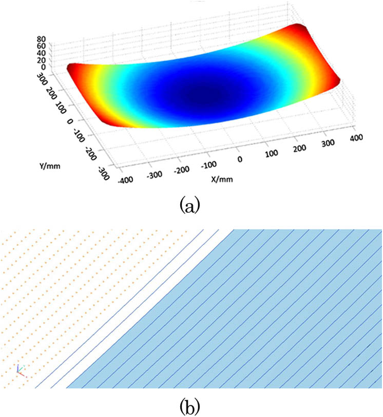
In order to establish a relatively high-accuracy optical freeform surface, optimization of the modeling method should be performed. The problem of accuracy loss caused by too-fast curvature change of the surface shape was solved. A feasible method to develop a high-precision freeform surface was developed. The realization process is shown as follows.
![]()
Figure 1.(a) Freeform surface model based on a Zernike polynomial; (b) fitted CAD model.
Generation and optimization of the tool path using a CAM function module was performed after the CAD model was set up. Tool path planning is one of the important factors affecting the quality of high-accuracy grinding. A spiral machining path is often used because the trajectory is simple, smooth, and easy to implement by controlling the turntable.
The traditional spiral machining path is shown in Fig.
![]()
Figure 2.Spiral center: (a) on the workpiece surface; (b) out of the workpiece surface.
Because of alignment error between the wheel axis and workpiece surface center, the spiral center of the workpiece surface always residual
The cutter axial planning is to control the tool axis direction, which refers to the process of machining, another important factor affecting the processing quality. The ideal tool axis direction is adjusted along with the surface shape changes, thereby leaving the tool machining state unchanged. There are three commonly used approaches for axial planning; namely vertical, parallel, and inclined processing. According to the need for freeform surface machining, we used the inclined-axis rotary ultrasonic grinding method (Fig.
![]()
Figure 3.Schematic of the inclined-axis rotary ultrasonic grinding method.
According to the aforementioned tool path and tool axis direction, and also combining with the machining parameters (such as cutting depth and feed rate) as well as nonprocessing parameters (such as cut-in, retreat back, and cutting feed), the cutter location file that contains the aforementioned data information (*.stl) can be eventually generated. The cutter location file cannot be directly placed into the machine tool and must develop a post-processing file according to the structural parameters of the machine. Depending on the postprocessing file, the NC program (*.nc) could be generated. In this work, the post-processing file was generated by introducing the ICAM company’s ICAM-POST software. Using the post-processing file, it is very convenient to change the cutter location file into computer number control (CNC) code which can be correctly executed.
A five-axis machining center of DMG Company was used in the grinding process. This machine has a nonstandard configuration of a 45° tilt axis (rocker), through which the axial direction of the cutter control can be achieved. Figure
![]()
Figure 4.Grinding of the freeform SiC mirror: (a) machine tool; (b) testing of shape error; (c) machining results.
A resin bond diamond wheel was used. During grinding, pouring cooling was used by using water-based coolant. After grinding, a three-coordinate measuring machine [Fig.
The PV value of surface error is reduced to 20 μm by 1 to 2 times error compensation machining. If the mirror blank were machined by the traditional method, namely grinding the best-fit spherical path, the surface shape error would be close to 1 mm. Therefore, the traditional grinding accuracy can be improved by 50 times using a direct grinding free-form surface.
After the five-axis grinding process, CNC grinding and polishing processes[
![]()
Figure 5.CNC lapping and polishing of the freeform silicon carbide mirror: (a) photo of machine; (b) convergence rate of surface error with lapping cycles.
By controlling the residence time of the lapping pad on the workpiece surface, and the pressure between the lapping head and the workpiece, the amount of material removal can be controlled. Figure
At the polishing stage, along with the decrease in the shape error, the surface shape error of the machined surface cannot be measured by a three-coordinate measuring machine. We used a CGH in examination of the surface shape error. The designed testing light path is shown in Fig.
![]()
Figure 6.(a) Testing optical path; (b) region function distribution of CGH; (c) photo of CGH; (d) testing results.
Except for the main measuring areas, the auxiliary function area, such as the alignment area and reference area, was also designed in order to attain precision adjustment and positioning. The final diffraction region distribution is shown in Fig.
The design work of CGH patterns was finished as soon as the optical structure and parameters were determined, through optimization of independently developed CGH design software. The diffraction region at the CGH compensator consists of a series of CGH fringes and is encoded into a GDS II file, according to which the CGH [Fig.
This Letter summarizes some processes and technologies during quick fabrication of a complex large-scale freeform silicon carbide mirror. During the grinding process, a new method of directly grinding according to a high-accuracy model is developed, which greatly reduces the subsequent CNC lapping time. This work also contributes to shortening the entire production cycle for a freeform optics element.
Aiming at the fact that a freeform surface cannot be tested using traditional refractive-type compensators, we design CGH compensation technology and use it to test a freeform surface. This CGH can also be used to align the light path, thus providing accurate positioning and also many other features. This work solves the reported problem that the traditional null lens compensator has no light path adjustment ability. A good testing result was obtained by using the aforementioned CGH technology.
References
[1] X. Zhang, J. Cao. Proc. SPIE, 4829, 884(2003).
[2] X. Zhang, D. Xue, M. Li, X. Zeng, Z. Zhang. Proc. SPIE, 8838, 88380N(2013).
[3] F. Li, J. Zhao, R. Li. Proc. SPIE, 7656, 765643(2010).
[4] Y. Choi, A. Banerjee. Int. J. Machine Tools Manuf., 47, 689(2007).

Set citation alerts for the article
Please enter your email address
© Copyright 2018-2021 | Chinese Laser Press. All Rights Reserved 沪ICP备15018463号-20