Shaoshuai Sui, Mingying Tang, Yuede Yang, Jinlong Xiao, Yun Du, and Yongzhen Huang*
Abstract
Hybrid octagonal-ring microlasers are investigated for realizing a stable output from a silicon waveguide based on a two-dimensional simulation. The inner radius of the ring is optimized to achieve single-mode and low-threshold operation. Using the divinylsiloxane-benzocyclobutene (DVS-BCB) bonding technique, a hybrid AlGaInAs/Si octagonal-ring microlaser vertically coupled to a silicon waveguide is fabricated with a side length of 21.6 μm and an inner radius of 15 μm. A single transverse-mode operation is achieved with a threshold current density of and a side-mode suppression ratio above 30 dB, and a stable output from the lower silicon waveguide is obtained.Silicon photonics integration is drawing more attention for its low-power consumption data transmission and large-scale integration capabilities due to its high-index contrast and compatibility with a mature CMOS process. An electrically pumped light source on silicon is essential for that[1–4]. As silicon is an indirect bandgap material with extremely poor light-emission efficiency, a hybrid integration of III/V gain material on silicon is proposed to solve this problem through bonding techniques such as direct bonding[5–7], metal bonding[8] and adhesive bonding[9–12]. Whispering gallery-mode microlasers are desirable light sources for photonic integrated circuits because of their high quality () factor, low power consumption, and small footprint. However, one shortcoming for microdisk and microring lasers bonded on silicon is the competition between clockwise (CW) and counter-clockwise (CCW) traveling-wave modes, which will lead to an unstable output power[13,14]. Additionally, in a microdisk or ring cavity, the single transverse-mode operation is difficult to achieve[15,16]. The single transverse mode is usually realized in a very narrow resonator[17]. For polygonal microlasers, a single transverse operation is easy to realize due to the large difference of the -factors between the fundamental and high-order transverse modes[18,19]. However, experimental polygonal microlasers on silicon have still not been reported.
In this Letter, a hybrid octagonal-ring microlaser coupled to a silicon waveguide is demonstrated theoretically and experimentally. A single transverse-mode operation is designed by optimizing the inner radius of the ring. A hybrid AlGaInAs/Si octagonal-ring microlaser with a side length of 21.6 μm and an inner radius of 15 μm is fabricated using the divinylsiloxane-benzocyclobutene (DVS-BCB) bonding technique. A single-mode operation is achieved with a threshold current density of and side-mode suppression ratio of 30 dB. A stable power output from the silicon waveguide is experimentally realized, which proves the elimination of the competition between the CW and CCW modes.
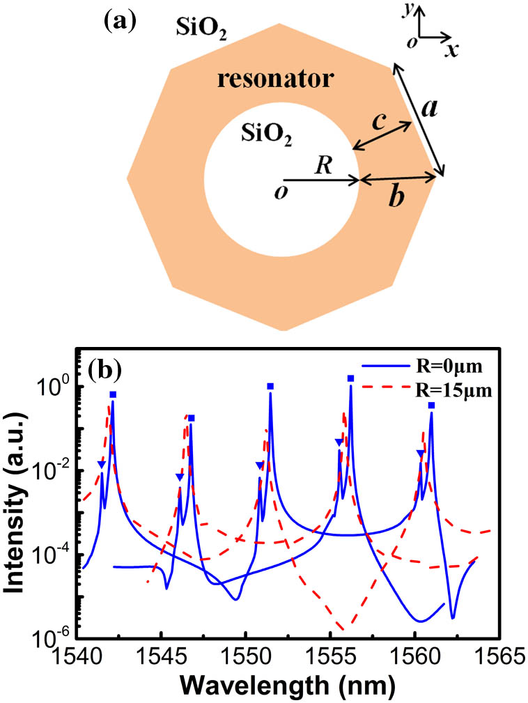
The mode characteristics of an octagonal-ring resonator are investigated for transverse electric (TE) polarized modes using the two-dimensional finite-element method. Figure 1(a) shows the schematic diagram of the octagonal-ring resonator with a refractive index of 3.2, surrounded by layers with a refractive index of 1.45. The octagonal-ring resonator has a side length , and the longest and shortest distances from the inner-ring edge to the outer edge are marked as and , respectively. We consider the influence of the inner radius on the mode characteristics. According to the Padé approximation[20], based on the finite-difference time-domain technique, the internal-field intensity spectra are calculated for TE modes in an octagonal-ring resonator and plotted in Fig. 1(b) as the solid and dashed lines at and 15 μm. Obviously, for , two sets of longitudinal modes marked as squares and triangles are found corresponding to the fundamental and first-order transverse modes, and the higher-order transverse modes are not obtained due to the low -factors. As increases to 15 μm, only fundamental-transverse mode is obtained as the first-order transverse modes with higher field intensity distribution in the internal region of octagonal-ring resonator are suppressed by enlarging the inner radius of ring.
Sign up for Chinese Optics Letters TOC. Get the latest issue of Chinese Optics Letters delivered right to you!Sign up now

Figure 1.Two-dimensional schematic diagram used in the numerical simulation, and (b) the calculated internal-field intensity spectra at and 15 μm.
The internal mode intensity distributions at are plotted in detail in Figs. 2(a) and 2(b) for the fundamental and the first-order transverse mode at the wavelengths of 1551.47 and 1550.82 nm, respectively, with -factors of and . Furthermore, the mode -factors are plotted as the functions of the inner radius in Fig. 3. The mode -factors remain almost constant, as is less than 10 μm due to the almost complete lack of field distributions in the center of the octagonal resonator. The modes of the -factors approach zero, as is larger than 17 and 13 μm for the fundamental and the first-order transverse modes, respectively. A sharp increase in the -factor is found before a rapid decrease, as for a microring cavity[21]. Therefore, an optimum range from 12 to 16 μm is obtained in order to achieve the single transverse-mode operation and keep a high -factor for the fundamental transverse modes.
Figure 2.Internal mode intensity distribution at for (a) fundamental transverse mode at 1551.47 nm and (b) first-order transverse mode at 1550.82 nm.
Figure 3.Mode -factor versus the inner radius for fundamental (squares) and first-order (triangles) transverse modes.
To clarify the mode competition between the CW and CCW traveling-wave modes in an octagonal resonator, the normalized intensities versus the angular momentum index are calculated for the fundamental and first-order transverse modes in Figs. 2(a) and 2(b), and plotted in Figs. 4(a) and 4(b). The positive and negative values of represent the CCW and CW traveling-wave components, respectively. Therefore, the standing-wave mode field distribution is obtained due to the strong coupling between the CW and CCW modes in an octagonal resonator, which ensures the equal outputs from the CW and CCW directions and eliminates the competition between the CW and CCW traveling-wave modes.
Figure 4.Normalized intensity versus the angular momentum index for (a) the fundamental and (b) the first-order transverse modes. Positive (negative) values of correspond to CCW (CW) traveling-wave components.
We fabricated hybrid octagonal-ring lasers coupled to an underlying silicon waveguide using an AlGaInAs/InP laser wafer grown on a p-InP substrate by metal-organic chemical vapor deposition. The laser wafer comprises a 150 nm InGaAsP etch-stop layer, a 0.1 μm heavily doped layer as the p-electrode contacting layer, a 1.2 μm p-InP up-cladding layer, eight compressively strained AlGaInAs quantum wells with a well thickness of 5 nm and a barrier thickness of 9 nm sandwiched between two 90 nm AlGaInAs separated, confined layers, and a 0.3 μm n-InP as the bottom-cladding and n-electrode contacting layer. Using i-line projection photolithography, the silicon bus waveguide is fabricated on a 4 inch SOI wafer, with a height of 350 nm and a width of 2 μm. Then, the SOI wafer is diced into pieces. Using the DVS-BCB bonding technique as in Ref. [15], the AlGaInAs/InP laser wafer with a size of is bonded on the patterned SOI wafer with a top silicon layer 350 nm thick and a buried oxide layer 1 μm thick.
The fabrication processes of hybrid octagonal-ring lasers are summarized as follows. Firstly, a 400 nm layer is deposited onto the bonded laser wafer by plasma-enhanced chemical vapor deposition (PECVD). The octagonal resonator patterns with a side length of 21.6 μm are transferred onto the layer using the standard contacting photolithography technique, and then the patterned layer is used as a hard mask to etch the AlGaInAs/InP wafer to the BCB bonding layer by the inductively coupled plasma (ICP) etching technique. Secondly, a 300 nm layer is deposited onto the bonded laser wafer by the PECVD technique, and a 15 μm-radius microdisk etch window is transferred at the octagonal resonator center using standard photolithography. Subsequently, the octagonal-ring resonator is fabricated through etching the and III/V semiconductor wafer using the ICP technique again, and a thin n-InP bottom layer is left as the contact layer. After that, a 250 nm insulating layer is deposited by the PECVD on the wafer. Final, an Au-Ge-Ni n-electrode layer inside the octagonal-ring resonator is deposited by electron-beam evaporation and lift-off techniques, a p-type contact window is etched on top of the ring resonator, and a Ti-Pt-Au p-electrode is deposited.
The top-view scanning electron microscope (SEM) image after the first-step ICP etching to the BCB bonding layer is shown in Fig. 5(a), and the microscope image of the hybrid octagonal-ring microlaser after metal electrode deposition is shown in Fig. 5(b). The distance from the underneath silicon waveguide to the octagonal resonator center is 22.5 μm, which ensures a long coupling region between the optical field inside the octagonal-ring resonator and the underneath silicon waveguide. Figure 5(c) shows the cross-sectional view SEM image of a hybrid octagonal-ring microlaser vertically coupled to a silicon waveguide. The silicon waveguide has a width of 2 μm and a height of 300 nm, and the thickness of the BCB above the silicon waveguide is about 80 nm.
Figure 5.(a) Top-view SEM image after the first-step ICP etching to the BCB bonding layer. (b) Top-view microscope image after metal electrode deposition. (c) Cross-sectional view SEM image of hybrid octagonal-ring laser coupled to a silicon waveguide.
After cleaving the silicon waveguide, the hybrid AlGaInAs/Si octagonal-ring microlaser with the p-side up is mounted on a thermoelectric cooler (TEC). The output powers are measured by butt-coupling a multimode fiber to the cleaved silicon waveguide end face, and then the lasing spectra are measured by an optical spectrum analyzer with a resolution of 0.1 nm. For a hybrid octagonal-ring laser with a side length of 21.6 μm and an inner radius of 15 μm, the output powers versus the injection currents (P-I curve) are plotted in Fig. 6(a); the pulsed injection current has a pulse duty of 10% and a pulse width of 100 ns at the TEC temperature of 285 K. The threshold current is 12 mA, corresponding to the threshold current density of . The output power monotonously increases with the injection current without the fluctuations in the microdisk and ring lasers[11,13]. The output powers from the other side of silicon waveguide are also measured, and are the same as that in Fig. 6(a), and the power fluctuations caused by the competition between the CW and CCW modes are not found in the PI curve as the injection current increases. One possible reason is that the strong coupling between the CW and CCW modes leads to standing-wave lasing in the octagonal-ring lasers, which ensures the identical and stable output from the silicon waveguide. A series resistance of 37 Ω at the threshold is calculated according to the continuous-wave voltage versus the current in Fig. 6(a). Considering the low thermal conductivities of the BCB and buried oxide layers, the continuous-wave lasing is not obtained due to the large temperature rise, but it can be achieved by designing a thermal shunt and improving the threshold current[15].
Figure 6.(a) Peak powers from the silicon waveguide versus the pulsed injection current. (b) Lasing spectra at pulsed injection currents of 13, 25, and 32 mA.
The lasing spectra at pulsed currents of 13, 25, and 32 mA are shown in Fig. 6(b), with the main lasing modes at 1547.4, 1551.9, and 1556.6 nm and side-mode suppression ratios of 8, 30.5, and 31.5 dB, respectively. Obviously, only fundamental transverse mode lasing is achieved because the high-order transverse modes are completely suppressed at , as shown in Fig. 3. The longitudinal mode interval is 4.21 nm at 1552 nm for the fundamental transverse mode.
In conclusion, we demonstrate a single-mode hybrid AlGaInAs/Si octagonal-ring microlaser vertically coupled to a silicon waveguide. The numerical simulation results indicate that single-mode operation can be obtained by optimizing the inner radius of the ring. Hybrid octagonal-ring lasers with a side length of 21.6 μm and an inner radius of 15 μm are fabricated, and single-mode operation is obtained with the low threshold current density of and a side-mode suppression ratio above 30 dB. The stable output indicates the elimination of the competition between the CW and CCW traveling-wave modes.
References
[1] S. Koehl, A. Liu, M. Paniccia. Opt. Photon. News, 22, 24(2011).
[2] M. Streshinsky, R. Ding, Y. Liu, A. Novack, C. Galland, A. E.-J. Lim, P. Guo-Qiang Lo, T. Baehr-Jones, M. Hochberg. Opt. Photon. News, 24, 32(2013).
[3] Y. Li, Y. Zhang, A. W. Poon. Photon. Res., 3, 5(2015).
[4] D. A. B. Miller. Proc. IEEE, 97, 1166(2009).
[5] A. W. Fang, H. Park, O. Cohen, R. Jones, M. J. Paniccia, J. E. Bowers. Opt. Express, 14, 9203(2006).
[6] D. Liang, M. Fiorentino, S. Srinivasan, J. E. Bowers, R. G. Beausoleil. IEEE J. Sel. Top. Quantum Electron., 17, 1528(2011).
[7] C. Zhang, S. Srinivasan, Y. B. Tang, M. J. R. Heck, M. L. Davenport, J. E. Bowers. Opt. Express, 22, 10202(2014).
[8] L. J. Yuan, L. Tao, H. Y. Yu, W. X. Chen, D. Lu, Y. P. Li, G. Z. Ran, J. Q. Pan. IEEE Photon. Technol. Lett., 25, 1180(2013).
[9] J. Van Campenhout, L. Liu, P. R. Romeo, D. Van Thourhout, C. Seassal, P. Regreny, L. Di Cioccio, J. M. Fedeli, R. Baets. IEEE Photon. Technol. Lett., 20, 1345(2008).
[10] L. Liu, R. Kumar, K. Huybrechts, T. Spuesens, E.-J. Geluk, T. de Vries, P. Regreny, D. Van Thourhout, R. Baets, G. Morthier. Nat. Photon., 4, 182(2010).
[11] S. S. Sui, M. Y. Tang, Y. D. Yang, J. L. Xiao, Y. Du, Y. Z. Huang. IEEE. Photon. J., 7, 1(2015).
[12] S. S. Sui, M. Y. Tang, Y. D. Yang, J. L. Xiao, Y. Du, Y. Z. Huang. IEEE J. Quantum Electron., 51, 2600108(2015).
[13] S. S. Sui, M. Y. Tang, Y. D. Yang, J. L. Xiao, Y. Du, Y. Z. Huang. Opt. Lett., 40, 4995(2015).
[14] A. W. Poon, Y. Zhang, L. Zhang. Proc. SPIE, 9394, 934312(2015).
[15] S. S. Sui, M. Y. Tang, Y. D. Yang, J. L. Xiao, Y. Du, Y. Z. Huang. Photon. Res., 3, 289(2015).
[16] M. Lei, K. Che, C. Guo, S. Luo, Z. Cai. Chin. Opt. Lett., 12, 071401(2014).
[17] K. Yao, G. Y. Feng, S. H. Zhou. Chin. Opt. Lett., 12, 022303(2014).
[18] J. D. Lin, Y. Z. Huang, Y. D. Yang, Q. F. Yao, X. M. Lv, J. L. Xiao, Y. Du. IEEE. Photon. J., 3, 756(2011).
[19] L. X. Zou, X. M. Lv, Y. Z. Huang, H. Long, J. L. Xiao, Q. F. Yao, J. D. Lin, Y. Du. IEEE J. Sel. Top. Quantum Electron., 19, 1501808(2013).
[20] W. H. Guo, W. J. Li, Y. Z. Huang. IEEE Microwave Wireless Compon. Lett., 11, 223(2001).
[21] X. W. Ma, X. M. Lv, Y. Z. Huang, Y. D. Yue, J. L. Xiao, Y. Du. J. Opt. Soc. Am. B, 31, 2773(2014).