Abstract
The sweep rate, sweep range, and coherence length of swept sources, respectively, determine the acquisition rate, axial resolution, and imaging range of optical coherence tomography (OCT). In this paper, we demonstrate a reconfigurable high-speed and broadband swept laser by time stretching of a flat spectrum femtosecond pulse train with over 100 nm bandwidth and a repetition rate of 100 MHz. By incorporating an optical modulator and utilizing appropriate dispersive modules, the reconfiguration of the swept source is demonstrated with sweep rates of 25 and 2.5 MHz. The 2.5 MHz swept source enables an imaging range of with 6 dB sensitivity roll-off in OCT, which is the longest imaging range ever reported for megahertz OCT.1. INTRODUCTION
Swept source optical coherence tomography (SS-OCT) is the most promising technology for next-generation OCT since it does not rely on any moving reference mirror, and has higher spectral resolution and acquisition rate than spectrometer-based spectral domain OCT [1,2]. SS-OCT adopts a high-speed balanced detector to acquire time-resolved interference signal and obtain the layered image of the sample with the Fourier transform of the interference spectrum. The key component of the SS-OCT system is the swept laser with a high sweep rate, wide sweep range, and long coherence length.
A variety of wavelength swept lasers have been developed for megahertz SS-OCT systems [1]. Conventional tunable lasers have a limited sweep rate owing to the limitation of the buildup of the new laser signals during the wavelength tuning. When a micro-electro-mechanical system (MEMS) structure is combined with the vertical cavity surface emitting laser (VCSEL), the sweep rate could be enhanced to [3,4] to enable a megahertz axial scan (A-scan) rate of SS-OCT. The VCSEL swept source also demonstrates a long coherence length to extend the imaging range of OCT to a few meters [5]. However, the sweep rate of VCSEL is hard to enhance to with practical sweep range because of the inertia limitation [3,4]. The high driving voltage, the nonlinear tuning response, and the low output power are the problems in the development of wavelength swept VCSELs. In 2006, Fourier domain mode-locked (FDML) laser was proposed to avoid the rebuilding of intracavity laser signals and enhance the fundamental sweep rate to [6]. The sweep rate of the FDML laser-based swept source could be enhanced to 6.7 MHz with a high-order buffering technique, but the sweep range is reduced to [7]. The major weakness of the FDML laser is the short coherence length [8,9]. Although state-of-art dynamic compensation of the cavity dispersion could significantly enhance the coherence length, it is very challenging to maintain the stable swept signal [10,11]. Discretization of the swept signal by comb filters [12] could extend the coherence length to [13]. However, the resolving of absolute positions of the images is the major challenge in the application of such swept sources [14]. To further enhance the sweep rate, time stretching of broadband ultrashort pulses is a more promising technique [15]. In 2006, Moon and Kim proposed to stretch a wideband supercontinuum pulse source in the time domain by a long dispersive fiber based on group velocity dispersion, of which the sweep rate could reach 5 MHz [16]. Time stretching of pulses generated by a mode-locked fiber laser could generate swept signals with ultrahigh sweep rate [17,18]. However, it is still challenging to obtain a highly coherent pulse source with a sufficiently wide spectrum because of the gain bandwidth limitation of the rare-earth doped fibers and strong nonlinear noise. Many efforts have been paid to extend the sweep range by developing a broadband mode-locked fiber laser and combining other nonlinear spectral expansion [17–20]. In 2018, Kang et al. reported a 44.5 MHz time-stretched swept source with a 10 dB bandwidth of 102 nm, which had the highest sweep rate ever reported for time-stretched swept sources with a practical sweep range of [21]. But, the spectrum generated from the mode locked fiber laser has a large slope, and the 3 dB bandwidth is only .
In this paper, we will demonstrate a reconfigurable time-stretched swept source based on a 100 MHz Figure-9 mode locked fiber laser with 100 nm sweep range. In Section 2, we will introduce the experimental setup of the reconfigurable swept source and the point spread function (PSF) characterization. Three configurations of the swept source with sweep rates of 2.5–100 MHz will be demonstrated in Section 3. The sensitivity roll-off of the OCT based on the swept sources will be characterized by the PSFs. Conclusions will be drawn in Section 4.
Sign up for Photonics Research TOC. Get the latest issue of Photonics Research delivered right to you!Sign up now
2. EXPERIMENTAL SETUP
A. Reconfigurable Time-Stretched Swept Source
Figure 1 shows the experimental setup of the swept laser, where a femtosecond mode-locked laser with a consecutive fiber amplifier is used as the seed signal of the system. An optical modulator combined with a pulse/pattern generator (PPG, Agilent, 81130A) is used to realize frequency division. A dispersion compensation module, which is either a section of dispersion compensation fiber (DCF) or a long chirped fiber Bragg grating (CFBG), is used to realize time stretching. The mode-locked laser is a custom-built Figure-9 laser (Menlo System, C-Fiber) with a dispersion matched erbium-doped fiber amplifier (EDFA), where the dispersions of the seed laser and fiber amplifier are carefully engineered to guarantee that the output pulse has a broad spectrum with 3 dB bandwidth of . Compared with the conventional femtosecond mode-locked fiber lasers based on the nonlinear amplified loop mirror (NALM) or nonlinear polarization rotation (NPR), the Figure-9 laser is much more stable since an all polarization maintaining fiber cavity is adopted [22]. Another advantage of such a configuration is the low loss working point on the transmission curve, which lowers the threshold to start mode locking [22]. The maximum transmission is achieved by the combination of a 45° Faraday rotator, a wave plate, a polarizing beam splitter, and a mirror. When a wave plate with a single pass phase retardation of is used, the small signal in the laser cavity works with the largest slope on the nonlinear transmission curve. With such a highly efficient cavity, a chirped pulse with a bandwidth of is generated from the seed laser. The 100 MHz repetition rate obtained with the compact cavity is much higher than that of conventional lasers with NPR or NALM configurations. The chirped pulse is then injected into the EDFA to simultaneously amplify and compress the pulse to , where the spectrum is further broadened to have a 3 dB bandwidth of 77 nm at the output.
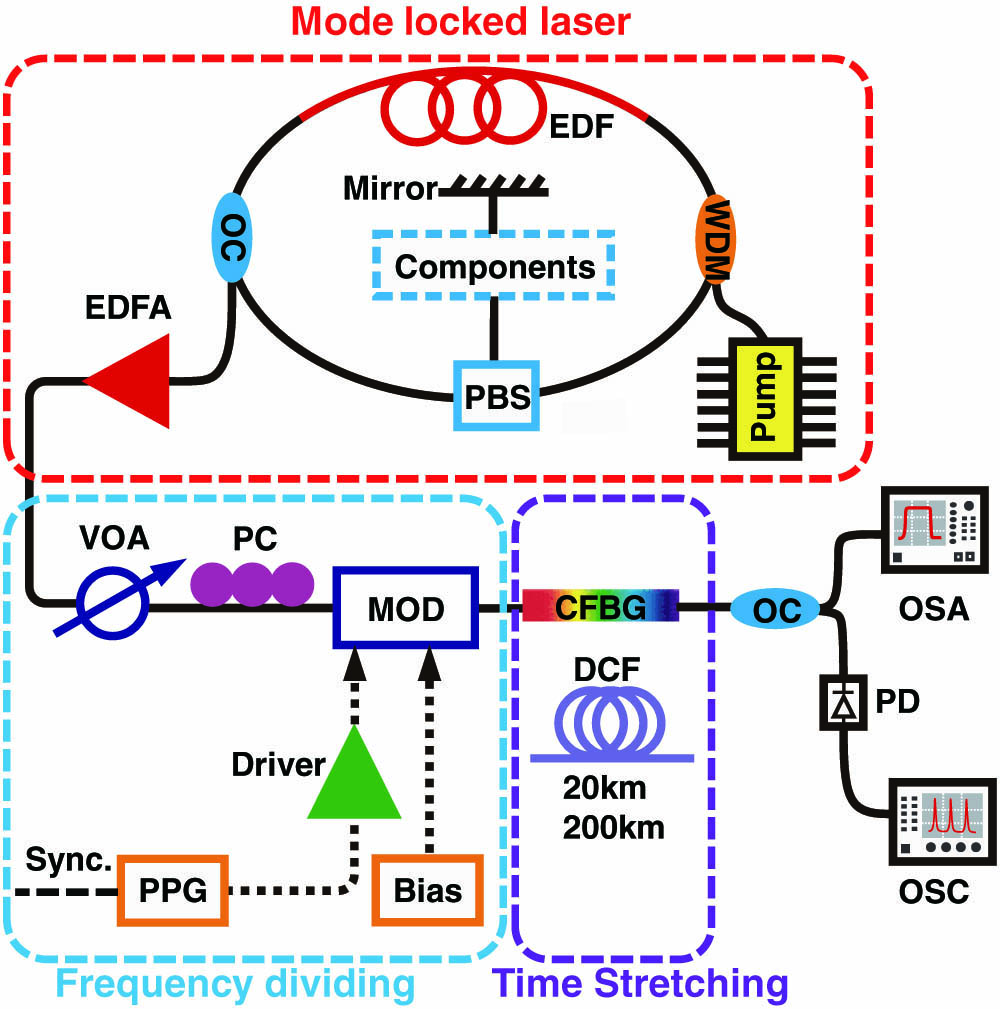
Figure 1.Experimental setup of the swept laser. WDM, wavelength division multiplexer; EDF, erbium-doped fiber; PBS, polarizing beam splitter; Components, Faraday rotator, wave plate, and polarizing beam splitter; OC, optical coupler; EDFA, erbium-doped fiber amplifier; VOA, variable optical attenuator; PC, polarization controller; PPG, pulse/pattern generator; MOD, optical modulator; CFBG, chirped fiber Bragg grating; DCF, dispersion compensation fiber; PD, photodetector; OSA, optical spectrum analyzer; OSC, oscilloscope.
The reconfiguration of the sweep rate is realized by modulating the 100 MHz optical pulse train with a low repetition rate electric pulse train. A 10 GHz Mach–Zehnder optical intensity modulator (JDS Uniphase, IOAP-MOD9140) is used after the EDFA to modulate the optical signal. A variable optical attenuator (ANDO, AQ-3105A) is utilized before the modulator to decrease the optical power in order to avoid nonlinear effects, which could deteriorate the coherence and simultaneously induce fluctuations on the spectrum. A small part of the output signal from the mode-locked fiber laser is injected into a photodetector to generate a clock signal with frequency for the PPG, which is used to generate a sequence of short square pulses with fractional frequency , where is an integer. By adjusting the number of ‘0’ bits (off) between adjacent ‘1’ bits (on) in the pattern, the repetition rate of the electric pulse train can be reconfigured. An optical modulator driver (JDS Uniphase, H301-1110) is used to amplify the electric pulse train to drive the modulator and an automatic bias controller (Plugtech, MBC-IQ-1) is used to dynamically lock the bias voltage at the “NULL” point of the modulator to ensure that the optical pulses at the “off” bits are completely suppressed. The polarization dependence of the modulation is controlled by a polarization controller.
The time stretching is the key process, where the ultrashort pulses are stretched by the dispersion modules such as a section of DCF or a CFBG to highly chirped long pulses with a sweep trace of [16] where is the group velocity dispersion coefficient and is the fiber length (only nominal for CFBG). The duration of the output pulse is where is the average dispersion in the spectral range of . DCF and CFBGs with different dispersions are used according to the reconfigured repetition rate. To verify the sweeping characteristic of the signals, signals of different wavelengths are selected by an optical tunable filter (OTF, Santec, OTF-930) with a 3 dB bandwidth of 0.3 nm ranging from 1525 to 1605 nm and captured by an amplified photodetector (APD, Newport, AD-300) and a 4 GHz oscilloscope (OSC1, Tektronix, CSA7404B) to measure the temporal positions. All the spectra are measured by an optical spectrum analyzer (OSA, Yokogawa AQ6370D).
B. Measurement of Point Spread Function and Imaging Range
Figure 2 shows the schematic diagram for the measurement of PSFs and imaging range. The swept laser output is amplified by a semiconductor optical amplifier (SOA, Thorlabs, BOA1004S) before being injected into the interference system, if necessary, to improve the sensitivity. The swept signal is split by a 50:50 coupler and injected into the two arms of the Michelson interferometer. Two homemade motorized reflective variable optical delay lines (VODLs) serve as the two arms, respectively. The reflected lights are routed into another 50:50 coupler by two circulators. Polarization controllers are used in the two arms to reduce the polarization difference between them. The interference signal combined in the coupler is detected by a balanced photodetector (Finisar, BPDV2150R) with a bandwidth of 43 GHz and then acquired by a high-speed real-time oscilloscope (OSC2, Tektronix, DPO75902SX ATI) with a bandwidth of 59 GHz and a sampling rate of 200 GSa/s. A synchronous signal generated by the swept source is used to trigger the oscilloscope to acquire the interference signal. Different delays between the sample arm and the reference arm could result in modulations on the temporal waveforms with different frequencies. The interference signals acquired by the oscilloscope are used to calculate the PSFs by Fourier transform. The details of PSF calculation will be discussed in next section.

Figure 2.Schematic diagram of the point spread function and imaging range measurement system. SOA, semiconductor optical amplifier; OSC, oscilloscope; OC, optical coupler; BPD, balanced photodetector; CIR, circulator; PC, polarization controller; VODL, variable optical delay line.
3. EXPERIMENTAL RESULTS AND DISCUSSION
In this section, we will demonstrate the swept sources based on the experimental setup shown in Section 2. Three configurations with sweep rates of 100 MHz, 25 MHz, and 2.5 MHz based on time stretching of femtosecond pulses in CFBGs and DCF will be characterized to demonstrate the ultrafast sweep rate, the flexible reconfiguration, and the ultralong imaging range, respectively.
A. Femtosecond Pulse with Ultrabroad and Flat Spectrum
From the configuration shown in Fig. 1, we obtain a femtosecond pulse with an ultrabroad and flat spectrum. Figure 3 shows the spectrum and the temporal waveform of the output pulse from the EDFA. The pump currents of the oscillator and the EDFA are carefully tuned to optimize the output spectrum. As shown in Fig. 3(a), the output spectrum has a “top-hat” profile with fluctuations less than 1 dB within a range of 73.7 nm and a 10 dB spectral bandwidth of 102.4 nm. Such a flat top spectrum is highly desirable in swept sources to ensure the uniformity of the intensities at different wavelengths. To the best of our knowledge, it is the flattest spectrum ever reported, with fluctuations of , in such a broad range of . More importantly, the spectrum has a high coherence. The optical pulse train is converted to an electrical signal by the APD and captured by OSC1 as shown in Fig. 3(b). The average output power of the EDFA is 100 mW. With the repetition rate of 100 MHz, the single pulse energy is calculated to be 1 nJ. The pulse train is further characterized by an autocorrelator (Femtochrome, FR-103HS). The pulse duration is measured to be 44 fs with a hyperbolic secant fitting of the autocorrelation trace, as shown in Fig. 3(c). With the 3 dB bandwidth 77.0 nm, the calculated time-bandwidth product of the ultrashort pulse is 0.421, which is close to the limit 0.315 and indicates a high coherence of the lasing modes.
Figure 3.Output performance of the mode-locked laser. (a) Spectrum, (b) pulse train, and (c) autocorrelation trace of the femtosecond laser source.
B. Ultrafast Flat Spectrum Time-Stretched Swept Source
In this subsection, we will demonstrate a swept source with a sweep rate of 100 MHz without any frequency division by time stretching of the ultrashort pulses in a long CFBG (Proximion AB, DCM-CB-10). The CFBG is designed to compensate 10 km G.652 single mode fiber (SMF) with a nominal total dispersion of at 1545 nm. The CFBG has a reflection bandwidth of 49.7 nm ranging from 1525.0 to 1574.7 nm, as shown by the red solid curve in Fig. 4(a). The black dotted and blue dashed curves, respectively, represent the input and output spectra of the CFBG with the femtosecond pulse train shown in Fig. 3 injected into the CFBG through a circulator. We note that the high sidelobe of the red solid curve, which is out of the reflection range of the CFBG, is spurious. The sidelobe is caused by the noise floor of the OSA when the intensity of the input light in that spectral region is very low. From Fig. 4(a), the reflected spectrum shown by the blue dashed curve is very flat in the whole 49.7 nm range because the reflection band of the CFBG locates fully in the flat region of the laser pulse spectrum. The output spectrum has very sharp edges with side mode suppression ratio, which allows the swept signal to have a high duty cycle without overlapping of adjacent pulses. The high duty cycle could help maximize the pulse duration and the imaging range without decreasing the sweep rate. Besides the high duty cycle, using CFBGs as dispersive elements has the advantages of low loss, low nonlinearity, low latency, and low weighting comparing with DCF, especially when large dispersion is required. Furthermore, the dispersion coefficient of a CFBG could be designed to be a constant in the whole reflection band to realize linear wavelength sweep in the space.
Figure 4.Output performance of the 100 MHz swept source by time stretching in a CFBG. (a) The reflectivity, input, and output spectra of the CFBG used in experiment. (b) The output stretched waveform from the CFBG. (c) Filtered spectra and (d) waveforms of the swept signal when the central wavelength is tuned from 1525 to 1575 nm. (e) The swept trace obtained from (c) and (d) with parabolic fitting of . (f) Roll-off performance of the SS-OCT with PSFs measured at different optical delays. (g) OCT axial resolution in air.
Figure 4(b) shows the output waveform of the swept signal. In the CFBG, the ultrashort pulses are stretched to long chirped pulses with a duration of 8.4 ns with sharp edges. To further verify the wavelength sweep trace, the spectra and the temporal waveforms of the filtered signals are recorded when the OTF is tuned from 1525 to 1573 nm, as shown in Figs. 4(c) and 4(d), respectively. The pulses for different wavelengths are clearly separated in the time domain, which confirms the wavelength sweep feature of the signal. The central wavelength versus temporal position of the pulse signals is measured and shown in Fig. 4(e). The wavelength is swept from the red to the blue region accordant to the normal dispersion of the CFBG. By parabolic fitting of the curve the dispersion at is , and the dispersion slope is . Taking the average dispersion and sweep range into Eq. (3), the measured pulse duration 8.4 ns is consistent with the calculation based on the reflection band of the CFBG.
The imaging range of the OCT system can be quantified by measuring the PSFs with different delays between the reference arm and the sample arm. Since the dispersion coefficient of the CFBG is not a constant at different wavelengths, the data points uniformly sampled in the time domain do not distribute uniformly in the frequency domain. Taking the higher order dispersion into account, we resample the data into the frequency domain uniformly with assistance of the dispersion curve. It should be noted that the starting point of each sampling period should be properly set to ensure the time to wavelength mapping is correctly resolved. In an OCT system, the starting point could be calibrated by an FBG or other wavelength markers. It is also feasible to calibrate the system by just data fitting to optimize the PSF profile because of the fixed sweep trace of the time-stretched swept source. Comparing with other tunable filter-based swept lasers, the sweep trace of the time-stretching-based swept source is more stable since it is only determined by the dispersion of the CFBG or DCF, whose profile is fixed after fabrication and will not be affected by the aging of the electronic devices of the system. The pulse timing jitter of femtosecond mode-locked laser is , which is several orders lower than the jitter of most signal generators to drive tunable filters. The low timing jitter and stable sweep trace will significantly reduce the frequency of calibration in the OCT systems.
Figure 4(f) shows the PSFs obtained at different delays. The maximum sensitivity is with an average input power of the interferometer of . The power of the swept signal could still be increased by reducing the loss of the variable attenuator to enhance the sensitivity, which does not significantly affect the sensitivity roll-off along the imaging range. The 6 and 10 dB sensitivity roll-off lengths are measured to be 5.7 and 7.3 mm, respectively. One of the PSFs is fitted by a Gaussian profile, and the axial resolution is measured to be 36 μm in air as shown in Fig. 4(g). It should also be noted that the square spectral profile reflected by the CFBG leads to high sidelobes on the PSF profile, which is suppressed in practice by a carefully engineered complex amplitude compensation applied on the interference spectrum before Fourier transforms. In Fig. 4(f), the signal to noise ratio (SNR) of the PSFs is observed to be , which is still lower than the typical SNR of 40 dB for SS-OCT. Such degradation of SNRs is always observed in our investigation with different CFBGs adopted in the time stretching, which is believed to be caused by the delay and phase ripples of the CFBG.
C. Reconfiguration of Time-Stretched Swept Source
In the subsection above, we demonstrated an ultrafast swept laser with 100 MHz sweep rate by time stretching of the broadband femtosecond pulse in a long CFBG. The adoption of CFBG as the dispersion element has obvious advantages such as low latency, low propagation loss, sharp spectral edges, high duty cycle, and possible linear sweeping. However, CFBG also brings unavoidable drawbacks into the system. The spectrum located outside the reflection bandwidth of the CFBG is wasted. In addition, fabrication of a long CFBG a few meters in length is still challenging, and currently the cost is times of that of the DCF for the same dispersion values. The ripples on delay and phase versus wavelength of the long CFBG [23] are another problem that may cause noise on the PSF. In the following subsections, the time stretching will be realized in multiple sections of DCF. Compared with SMF, adopting DCF in the time stretching has a higher figure of merit since it could provide times of dispersion with about 3 times of loss in the same length.
Although the high sweep rate is desirable to enhance the A-scan rate of OCT, it also increases the requirement of the detection system to capture enough sampling points in the short sweep period. A reconfigurable swept source where the sweep rate could be adjusted will afford more flexible choices to satisfy different requirements with reasonable performance and cost. In this subsection, an optical modulator is incorporated into the laser system to divide the repetition rate of the pulse train, as shown by the frequency dividing block in Fig. 1. Figure 5(a) shows the output spectrum of the swept source with a center wavelength of 1555 nm, where 3 and 10 dB bandwidths of 73 and 95 nm are observed, respectively. When compared with the mode-locked laser spectrum demonstrated in Fig. 3(a), the bandwidth is slightly narrowed by the finite working bandwidth of the modulator. By adjusting the separation of “1” bits on the PPG, the repetition rate of the pulse train can be reconfigured to 100/N MHz () in a large scale to fully cover the range of 1–100 MHz, which is most desirable in OCT systems. The extinction ratio is higher than 20 dB to ensure the suppression of the “off” bits. When the repetition rate of the pulse train is adjusted, the dispersion element should be reconfigured to provide a suitable dispersion to stretch the pulse to fill the period but without overlap to adjacent pulses. In experiment, we use various sections of DCF with different nominal dispersions individually or jointly to realize the time stretching for different sweep rates.
Figure 5.Output performance of the 25 MHz swept source by time stretching in DCF. (a) The output spectrum of swept source with a reconfigured sweep rate of 25 MHz. (b) The waveforms before and after time stretching in DCF. (c) The swept trace with parabolic fitting from 1525 to 1605 nm. (d) Roll-off performance of the SS-OCT with PSFs measured at different optical delays. (e) OCT axial resolution in air.
Figure 5(b) shows an example of a frequency divided pulse train with a final repetition rate of 25 MHz. The waveforms before and after time stretching are denoted by the blue and the red curves, respectively. The time stretching is realized in a section of DCF (Accelink, DCM-20) with a nominal dispersion of at 1545 nm for the compensation of 20 km G.652 SMF. The ultrashort pulses are stretched to long pulses with a full width at half-maximum (FWHM) of 23.9 ns and a 10% height duration of 32.3 ns. The relatively large difference between the FWHM and the 10% height duration is caused by the pedestal of the pulse, which is significant on the rising edge and corresponds to the gentle slope on the long wavelength side of the spectrum. The adoption of DCF has enabled the swept signal to cover the whole spectrum shown in Fig. 5(a) without wasting of any spectrum. The sweep trace of the signal is shown in Fig. 5(c) with the same method used in Figs. 4(c)–4(e), while the tuning range is 1525–1605 nm. A parabolic fitting of the swept signal demonstrates an of 0.99998. The measured total dispersion , and the dispersion slope at 1545 nm.
The swept signal with an average power of is then launched into the interferometer system, and the PSFs with different delays are shown in Fig. 5(d) to characterize the sensitivity roll-off. From the average power and the sweep rate 25 MHz, the maximum sensitivity is . The 6 and 10 dB sensitivity roll-off lengths are 13.6 and 17.6 mm, respectively, which are more than twice of that with CFBG in Fig. 4. The roll-off length is doubled with the increase of total dispersion from to , indicating that the imaging range is limited by the detector and data acquisition but not the coherence length of the swept source [24]. Figure 5(e) shows that the axial resolution measured with a Gaussian fitting to one of the PSF peaks is 25 μm, which is improved by using the full spectrum when compared with the result with CFBG. Besides the enhancement in resolution, the sidelobes on the PSFs are also lower than that with CFBG. The noise floor of the PSFs with DCF is lower than that with CFBG, which leads to an SNR of more than 40 dB. The difference on noise floor has been confirmed by multiple datasets with different lengths of CFBGs and DCF.
Except for the demonstrated 25 MHz swept source, multiple sweep rates have been realized in our experiments. We noted that when the sweep rate is reduced, the imaging range will be enhanced simultaneously. Such a flexible swept source provides a good solution to balance the requirements on an ultrahigh sweep rate and long imaging range in SS-OCT applications such as endoscopic lumen imaging [25] and industrial inspections [5,26–28]. The flexible swept source is also a good candidate of sources for multiscale light detection and ranging (LiDAR) [29].
D. Time-Stretched Swept Source with Ultralong Detection Range
In the above subsection, we demonstrated the reconfiguration of an ultrahigh speed swept source with up to 100 MHz sweep rate. In the OCT system, the imaging range is also an important feature in applications. A long imaging range of the OCT will relax the positioning tolerance of the probe in large-scale endoscopic imaging of lumina or stomach [25,30]. Besides biomedical imaging, long-range OCT could be used in industrial inspection [26,27] and 3-D model construction [5,28]. Besides the application in OCT, long detection range is also the most desirable feature for swept source LiDAR [29].
In the reconfiguration of the swept source, the imaging range is found to be nearly proportional to the pulse duration of the swept signal. Thus, the imaging range of the SS-OCT system can be increased by incorporating with larger dispersion value to obtain a longer pulse. To obtain an ultralong chirped pulse, three sections of DCF (YOSC DCM-, OFS DCM-40) with a total nominal dispersion of at 1545 nm to compensate 200 km G.652 SMF are jointly used in the experiment. The sweep rate is reconfigured to 2.5 MHz to fit the pulse duration with the period, which is sufficiently high for most OCT applications. Since of the input power is attenuated by the modulator and DCF, an SOA is used to amplify the signal after time stretching in the DCF. Figure 6(a) shows the spectrum of the amplified swept signal with a 10 dB bandwidth of 75.0 nm, which is narrower than that of the input spectrum due to the bandwidth limitation of the modulator, the SOA, and nonlinear effect in the long DCF. The center wavelength of the spectrum is shifted to 1563 nm by the amplification. The fluctuations of the spectrum are mainly due to the polarization dependence of the SOA. Figure 6(b) shows the pulse trains before (blue curves) and after (red curves) the stretching in DCF and amplification. The stretched pulse has an FWHM duration of 214.2 ns. The sweep trace of the signal is also characterized as shown in Fig. 6(c). A total dispersion and a dispersion slope at 1545 nm are obtained by the parabolic fitting with an of 0.99998.
Figure 6.Output performance of 2.5 MHz swept source by time stretching in DCF. (a) The output spectrum of the swept source with a reconfigured sweep rate of 2.5 MHz. (b) The waveforms before and after time stretching in DCF. (c) The swept trace with parabolic fitting from 1525 to 1605 nm. (d) Roll-off performance of the SS-OCT with PSFs measured at different optical delays. (e) OCT axial resolution in air.
The 2.5 MHz swept signal with an average power of is injected into the interferometer, and the sensitivity roll-off lengths are characterized by the PSFs with different delays as shown in Fig. 6(d). The maximum sensitivity of the OCT is . As expected, the imaging range is enhanced to 111 and 127 mm with 6 and 8 dB sensitivity roll-off, which is the longest imaging range ever reported for megahertz OCT. The sensitivity roll-off is still less than 10 dB at 127 mm; however, it is the longest distance of the VODL used in the experiment. The PSFs show an SNR of and an axial resolution of 22 μm as shown in Fig. 6(e), which are in accordance to the results with 25 MHz swept signal shown in Fig. 5.
E. Comparison and Discussion
In the above subsections, we demonstrated a reconfigurable swept source based on a flat top spectrum femtosecond fiber laser. The swept source has shown distinct performances including ultrafast sweep rate, long imaging range, and flexible reconfiguration. In Table 1, we summarize the performance measured with the three configurations demonstrated. The three configurations, respectively, demonstrate different merits of the swept source.
| Sweep Rate | Dispersion Element | Pulse FWHM | 10 dB Bandwidth | Sensitivity | Axial Resolution | 6 dB Roll-Off Length |
| 100 MHz | CFBG, −10 km G.652, −165 ps/nm | 8.4 ns | 49.7 nm | 80 dB | 36 μm | 5.7 mm |
| 25 MHz | DCF, −20 km G.652, −322 ps/nm | 23.9 ns | 95 nm | 77 dB | 25 μm | 13.6 mm |
| 2.5 MHz | DCF, −200 km G.652, −3306 ps/nm | 214.2 ns | 75 nm | 95 dB | 22 μm | 111 mm |
Table 1. Performance of Swept Laser Sources with Different Configurations
The first configuration shows an ultrafast swept source with a sweep rate of 100 MHz. Besides the ultrahigh sweep rate, the roll-off length of sensitivity reaches the length of 5.7 mm, which is comparable to most tunable filter-based swept sources, such as FDML lasers [6] and MEMS filter-based external cavity diode lasers [31]. It should be noted that the long imaging range is obtained with a 43 GHz photodetector and a 59 GHz oscilloscope. Such a high-speed data acquisition rate could not be maintained for a long duration because of the limit of the data processing capacity of computers. However, the ultrafast sweep rate could be utilized in imaging of fast-moving objects or transient dynamics of interested targets, which only last a short duration of time. The adoption of the CFBG as the dispersion element leads to very sharp edges on both the spectrum and the temporal waveform of the pulse, which may allow a nearly 100% duty cycle if the CFBG and the sweep rate are matched. Compared with DCF, the dispersion slope of the CFBG can be finely controlled, and it is possible to fabricate a CFBG with nonzero and for a linear frequency sweep, which is impossible to obtain in DCF. The main limitation of adoption of CFBG comes from the high cost at least for now. Once a CFBG is fabricated, it is impossible for it to be cut and spliced, and the total dispersion is fixed. Hence, CFBG is less flexible when compared with DCF.
Adoption of DCF could improve the axial resolution by using the full spectrum, at the expense of a lower duty cycle. We note that a CFBG with low dispersion could be jointly used with DCF to obtain a high duty cycle for flexible large dispersion stretching with a relatively low cost. Massively produced DCF is more competitive in cost than CFBG. It is also convenient to cut and splice DCF to obtain a total dispersion of any desirable value. In the reconfiguration of the swept source, we use different sections of DCF to realize the time stretching of pulse into different durations. In practice, optical switches could be used to connect multiple sections of DCF to reconfigure the total dispersion with only a small power penalty as the insertion loss of commercially available optical switches is [32]. For example, five sections of DCF with compensation lengths of 100, 60, 40, 20, and 10 km of G.652 SMF could be sequentially connected into the fiber link with 10 pieces of optical switches. All the 25 dispersion values from 10 to 250 km by a step size of 10 km can be obtained with different combinations of the states of the switches. The total power penalty of the optical switches should typically be . The selection of the working wavelength in the region of 1550 nm is another important factor to enable the high performance of the swept source despite the fact that 1550 nm may not be suitable for some OCT applications such as retina imaging because of the high absorption in vitreous humor. Currently, the highly dispersive low loss DCF is only commercially available in 1550 nm region. It is also important to use fibers with opposite dispersions in the fiber laser cavity to engineer the total dispersion, which is difficult at 1060 nm since anomalous dispersion step-index SMF is not available. The flexible reconfiguration is desirable in multiscale detection systems such as the swept source LiDAR [29], where switchable fast detection and long-range detection modes will relax the requirement of the detection module.
When the response speed of the detector and data acquisition is given, the imaging range of the swept source OCT is nearly proportional to the total dispersion used in the time stretching [21]. In the second configuration demonstrated with a 25 MHz sweep rate, the sensitivity roll-off length is increased by more than twice when the dispersion value is doubled, owing to the lower phase jitters of the DCF when compared with the CFBG. When the dispersion is increased from to , the roll-off length is increased from 13.6 mm to 111 mm, which is the longest imaging range of megahertz OCT ever reported. The long imaging range also benefits from the high-speed detection system used in the experiment besides the high coherence of the swept source. If the bandwidth of the detection module is decreased in application, the imaging range will decrease proportionally. In practice, the sweep rate of 2.5 MHz is sufficiently high for most applications including video-rate volumetric OCT imaging. The long detection range will extend the application of such a swept source into different fields such as industrial inspection, 3-D model construction, and LiDAR.
4. CONCLUSION
In this paper, we demonstrate a reconfigurable swept source for OCT by time stretching of a broadband femtosecond pulse train in a CFBG and DCFs. The femtosecond pulse train is generated from an amplified mode-locked fiber laser with a repetition rate of 100 MHz. The output spectrum has a “top-hat” profile with a 1 and 10 dB bandwidth of 73.7 and 102.4 nm, respectively. In the dispersive elements, the femtosecond pulse trains are stretched into long swept pulses. The 100 nm sweep range is comparable to conventional swept lasers with SOA such as FDML lasers, but the sweep rate is increased by 3 orders of magnitude. By incorporating a frequency divider, the sweep rate can be reconfigured in the range of 2.5–100 MHz. By using a long CFBG as the dispersion element, a sharp edge swept signal with 100 MHz sweep rate, 49.7 nm sweep range, and 83% duty cycle is obtained. The swept signal demonstrates a sensitivity roll-off length of 5.7 mm and an axial resolution of 36 μm in the OCT characterization. When the sweep rate of the swept source is reduced by the frequency divider, the sensitivity roll-off length is further increased. With a sweep rate of 25 MHz and time stretching in a section of DCF to compensate 20 km G.652 SMF, the 6 dB sensitivity roll-off length is 13.6 mm with an axial resolution of 25 μm. When the sweep rate is decreased to 2.5 MHz and a section of DCF with 200 km nominal compensation length is used, the 6 dB sensitivity roll-off length is boosted to 111 mm. It is the first time that the 6 dB sensitivity roll-off length of megahertz SS-OCT is enhanced to more than 100 mm. Besides the application in SS-OCT to enhance the imaging performance, such a flexible highly coherent ultrafast swept source could also be adopted in detection applications such as LiDAR.
References
[1] T. Klein, R. Huber. High-speed OCT light sources and systems [Invited]. Biomed. Opt. Express, 8, 828-859(2017).
[2] A. F. Fercher, W. Drexler, C. K. Hitzenberger, T. Lasser. Optical coherence tomography—principles and applications. Rep. Prog. Phys., 66, 239-303(2003).
[3] P. Qiao, K. T. Cook, K. Li, C. J. Chang-Hasnain. Wavelength-swept VCSELs. IEEE J. Sel. Top. Quantum Electron., 23, 1700516(2017).
[4] K. T. Cook, P. Qiao, J. Qi, L. A. Coldren, C. J. Chang-Hasnain. Resonant-antiresonant coupled cavity VCSELs. Opt. Express, 27, 1798-1807(2019).
[5] Z. Wang, B. Potsaid, L. Chen, C. Doerr, H.-C. Lee, T. Nielson, V. Jayaraman, A. E. Cable, E. Swanson, J. G. Fujimoto. Cubic meter volume optical coherence tomography. Optica, 3, 1496-1503(2016).
[6] R. Huber, M. Wojtkowski, J. G. Fujimoto. Fourier domain mode locking (FDML): a new laser operating regime and applications for optical coherence tomography. Opt. Express, 14, 3225-3237(2006).
[7] T. Klein, W. Wieser, L. Reznicek, A. Neubauer, A. Kampik, R. Huber. Multi-MHz retinal OCT. Biomed. Opt. Express, 4, 1890-1908(2013).
[8] B. R. Biedermann, W. Wieser, C. M. Eigenwillig, T. Klein, R. Huber. Dispersion, coherence and noise of Fourier domain mode locked lasers. Opt. Express, 17, 9947-9961(2009).
[9] W. Wieser, T. Klein, D. C. Adler, F. Trépanier, C. M. Eigenwillig, S. Karpf, J. M. Schmitt, R. Huber. Extended coherence length megahertz FDML and its application for anterior segment imaging. Biomed. Opt. Express, 3, 2647-2657(2012).
[10] T. Pfeiffer, M. Petermann, W. Draxinger, C. Jirauschek, R. Huber. Ultra low noise Fourier domain mode locked laser for high quality megahertz optical coherence tomography. Biomed. Opt. Express, 9, 4130-4148(2018).
[11] S. Slepneva, B. O’shaughnessy, A. G. Vladimirov, S. Rica, E. A. Viktorov, G. Huyet. Convective Nozaki–Bekki holes in a long cavity OCT laser. Opt. Express, 27, 16395-16404(2019).
[12] T.-H. Tsai, C. Zhou, D. C. Adler, J. G. Fujimoto. Frequency comb swept lasers. Opt. Express, 17, 21257-21270(2009).
[13] D. Huang, F. Li, C. Shang, Z. Cheng, S. T. Chu, P. K. A. Wai. Frequency comb swept laser with a high-Q microring filter. Photon. Res., 8, 904-911(2020).
[14] N. Lippok, M. Siddiqui, B. J. Vakoc, B. E. Bouma. Extended coherence length and depth ranging using a Fourier-domain mode-locked frequency comb and circular interferometric ranging. Phys. Rev. Appl., 11, 014018(2019).
[15] A. Mahjoubfar, D. V. Churkin, S. Barland, N. Broderick, S. K. Turitsyn, B. Jalali. Time stretch and its applications. Nat. Photonics, 11, 341-351(2017).
[16] H. Song, S. B. Cho, D. U. Kim, S. Jeong, D. Y. Kim. Ultra-high-speed phase-sensitive optical coherence reflectometer with a stretched pulse supercontinuum source. Appl. Opt., 50, 4000-4004(2011).
[17] B. Li, X. Wei, S. Tan, J. Kang, K. K. Y. Wong. Compact and stable temporally magnified tomography using a phase-locked broadband source. Opt. Lett., 41, 1562-1565(2016).
[18] B. Li, C. Zhang, J. Kang, X. Wei, S. Tan, K. K. Y. Wong. 109 MHz optical tomography using temporal magnification. Opt. Lett., 40, 2965-2968(2015).
[19] X. Wei, A. K. S. Lau, Y. Xu, K. K. Tsia, K. K. Y. Wong. 28 MHz swept source at 1.0 μm for ultrafast quantitative phase imaging. Biomed. Opt. Express, 6, 3855-3864(2015).
[20] S. Tan, L. Yang, X. Wei, C. Li, N. Chen, K. K. Tsia, K. K. Y. Wong. High-speed wavelength-swept source at 2.0 μm and its application in imaging through a scattering medium. Opt. Lett., 42, 1540-1543(2017).
[21] J. Kang, P. Feng, X. Wei, E. Y. Lam, K. K. Tsia, K. K. Y. Wong. 102-nm, 44.5-MHz inertial-free swept source by mode-locked fiber laser and time stretch technique for optical coherence tomography. Opt. Express, 26, 4370-4381(2018).
[22] W. Hänsel, H. Hoogland, M. Giunta, S. Schmid, T. Steinmetz, R. Doubek, P. Mayer, S. Dobner, C. Cleff, M. Fischer, R. Holzwarth. All polarization-maintaining fiber laser architecture for robust femtosecond pulse generation. Appl. Phys. B, 123, 41(2017).
[23] M. Sumetsky, B. Eggleton, C. M. de Sterke. Theory of group delay ripple generated by chirped fiber gratings. Opt. Express, 10, 332-340(2002).
[24] J. Xu, X. Wei, L. Yu, C. Zhang, J. Xu, K. K. Y. Wong, K. K. Tsia. Performance of megahertz amplified optical time-stretch optical coherence tomography (AOT-OCT). Opt. Express, 22, 22498-22512(2014).
[25] M. J. Gora, M. J. Suter, G. J. Tearney, X. Li. Endoscopic optical coherence tomography: technologies and clinical applications [Invited]. Biomed. Opt. Express, 8, 2405-2444(2017).
[26] F. Hou, M. Zhang, Y. Zheng, L. Ding, X. Tang, Y. Liang. Detection of laser-induced bulk damage in optical crystals by swept-source optical coherence tomography. Opt. Express, 27, 3698-3709(2019).
[27] S. Song, J. Xu, R. K. Wang. Long-range and wide field of view optical coherence tomography for in vivo 3D imaging of large volume object based on akinetic programmable swept source. Biomed. Opt. Express, 7, 4734-4748(2016).
[28] I. Grulkowski, J. J. Liu, B. Potsaid, V. Jayaraman, J. Jiang, J. G. Fujimoto, A. E. Cable. High-precision, high-accuracy ultralong-range swept-source optical coherence tomography using vertical cavity surface emitting laser light source. Opt. Lett., 38, 673-675(2013).
[29] Y. Jiang, S. Karpf, B. Jalali. Time-stretch LiDAR as a spectrally scanned time-of-flight ranging camera. Nat. Photonics, 14, 14-18(2020).
[30] T.-H. Tsai, J. Fujimoto, H. Mashimo. Endoscopic optical coherence tomography for clinical gastroenterology. Diagnostics, 4, 57-93(2014).
[31] Axsun Technologies. Swept Lasers for OCT. Axsun Technologies(2020).
[32] . 1×2 Fiber Optical MEMS Switch Kit, USB/Push Button—Fiber-Fiber. Agiltron(2020).

