• High Power Laser Science and Engineering
  • Vol. 10, Issue 4, 04000e26 (2022)
A. X. Li1、2、3, C. Y. Qin1、3, H. Zhang1、4、*, S. Li1, L. L. Fan1、3, Q. S. Wang1、5, T. J. Xu1, N. W. Wang1, L. H. Yu1, Y. Xu1, Y. Q. Liu1, C. Wang1, X. L. Wang1, Z. X. Zhang1, X. Y. Liu1, P. L. Bai1, Z. B. Gan1, X. B. Zhang1, X. B. Wang1, C. Fan1, Y. J. Sun1, Y. H. Tang1, B. Yao1, X. Y. Liang1、4, Y. X. Leng1、4, B. F. Shen1、6、*, L. L. Ji1、4、*, R. X. Li1、2、4、*, and Z. Z. Xu1
Author Affiliations
  • 1State Key Laboratory of High Field Laser Physics, Shanghai Institute of Optics and Fine Mechanics, Chinese Academy of Sciences, Shanghai201800, China
  • 2ShanghaiTech University, Shanghai201210, China
  • 3Center of Materials Science and Optoelectronics Engineering, University of Chinese Academy of Sciences, Beijing100049, China
  • 4CAS Center for Excellence in Ultra-intense Laser Science, Shanghai201800, China
  • 5College of Science, University of Shanghai for Science and Technology, Shanghai200093, China
  • 6Department of Physics, Shanghai Normal University, Shanghai200234, China
  • show less
    DOI: 10.1017/hpl.2022.17 Cite this Article Set citation alerts
    A. X. Li, C. Y. Qin, H. Zhang, S. Li, L. L. Fan, Q. S. Wang, T. J. Xu, N. W. Wang, L. H. Yu, Y. Xu, Y. Q. Liu, C. Wang, X. L. Wang, Z. X. Zhang, X. Y. Liu, P. L. Bai, Z. B. Gan, X. B. Zhang, X. B. Wang, C. Fan, Y. J. Sun, Y. H. Tang, B. Yao, X. Y. Liang, Y. X. Leng, B. F. Shen, L. L. Ji, R. X. Li, Z. Z. Xu. Acceleration of 60 MeV proton beams in the commissioning experiment of the SULF-10 PW laser[J]. High Power Laser Science and Engineering, 2022, 10(4): 04000e26 Copy Citation Text show less
    The layout of the SULF laser facility[20" target="_self" style="display: inline;">20].
    Fig. 1. The layout of the SULF laser facility[20].
    The experimental area in USAP.
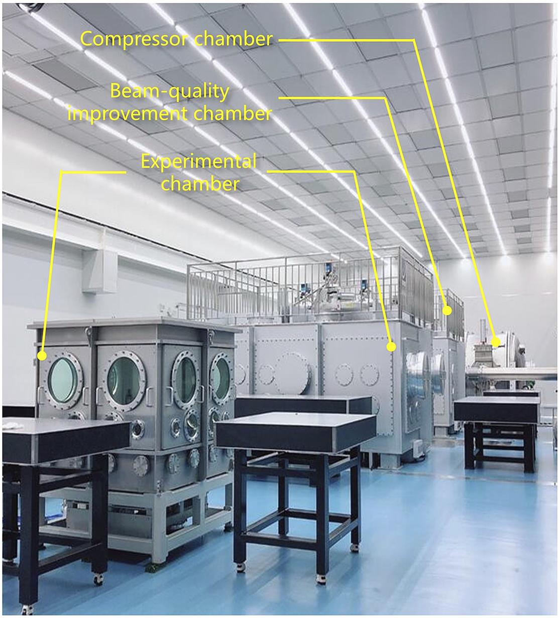
    Fig. 2. The experimental area in USAP.
    Laser parameters of the SULF-10 PW beamline for the commissioning experiment. (a) The typical focal spot of the laser after the correction of the double DM system, which is measured using a low-noise CCD by the light path built after an f/4.4 OAP. (b) The typical pulse duration of the compressed pulse measured by a Fastlite Wizzler instrument. The temporal contrast of (c) the nanosecond scale measured by a photodiode with a stack of neutral attenuators and (d) the picosecond scale measured by a third-order cross-correlator. The red arrow represents the saturated peak of the laser pulse.
    Fig. 3. Laser parameters of the SULF-10 PW beamline for the commissioning experiment. (a) The typical focal spot of the laser after the correction of the double DM system, which is measured using a low-noise CCD by the light path built after an f/4.4 OAP. (b) The typical pulse duration of the compressed pulse measured by a Fastlite Wizzler instrument. The temporal contrast of (c) the nanosecond scale measured by a photodiode with a stack of neutral attenuators and (d) the picosecond scale measured by a third-order cross-correlator. The red arrow represents the saturated peak of the laser pulse.
    The sketch of the experimental setup. The specially designed stacks of radiochromic films and BAS-SR image plates are used to measure the profile and energy spectrum of protons and electrons. The stacks and targets can move along the y direction. Two Thomson parabola spectrometers are used to detect the ion spectra at the target normal direction and laser direction. It installs six BAS-TR image plates at a time.
    Fig. 4. The sketch of the experimental setup. The specially designed stacks of radiochromic films and BAS-SR image plates are used to measure the profile and energy spectrum of protons and electrons. The stacks and targets can move along the y direction. Two Thomson parabola spectrometers are used to detect the ion spectra at the target normal direction and laser direction. It installs six BAS-TR image plates at a time.
    (a) The proton cut-off energy as a function of the target thickness of the plain Cu foils measured by TP1 in the target normal direction (red squares) and by both TP2 and RCF stacks in the laser propagation direction (blue circles), where the red and blue lines represent the average proton energy over two to three shots. The vertical error bars for some data are defined by the energy interval between adjacent RCF layers. (b) Typical proton spectra for five target thicknesses of l = 1 μm (black line), 2 μm (blue line), 4 μm (red line), 7 μm (magenta line) and 10 μm (cyan line) in the target normal direction, respectively. The proton energy spectrum for l = 4 μm (dashed red line) in the laser direction is also included in (b). (c), (d) The raw IP data of TP1 and TP2 for the best result of proton acceleration from a shot on a 4-μm Cu foil, where the inset in (c) is a magnified image of the ion trace in the high-energy region.
    Fig. 5. (a) The proton cut-off energy as a function of the target thickness of the plain Cu foils measured by TP1 in the target normal direction (red squares) and by both TP2 and RCF stacks in the laser propagation direction (blue circles), where the red and blue lines represent the average proton energy over two to three shots. The vertical error bars for some data are defined by the energy interval between adjacent RCF layers. (b) Typical proton spectra for five target thicknesses of l = 1 μm (black line), 2 μm (blue line), 4 μm (red line), 7 μm (magenta line) and 10 μm (cyan line) in the target normal direction, respectively. The proton energy spectrum for l = 4 μm (dashed red line) in the laser direction is also included in (b). (c), (d) The raw IP data of TP1 and TP2 for the best result of proton acceleration from a shot on a 4-μm Cu foil, where the inset in (c) is a magnified image of the ion trace in the high-energy region.
    (a) Typical proton profiles from three shots on Cu targets of l = 1, 4 and 10 μm at selected layers of RCF stacks corresponding to the proton energies of 11.6, 23.8, 32.2, 44.3 and 52.1 MeV, respectively. The target normal direction (0°) and laser direction (15°) are illustrated by dashed blue and red lines for 11.6 and 32.2 MeV. (b) Divergent angles of protons at different energies for l = 1 μm (blue circles), 4 μm (red squares) and 10 μm (black triangles).
    Fig. 6. (a) Typical proton profiles from three shots on Cu targets of l = 1, 4 and 10 μm at selected layers of RCF stacks corresponding to the proton energies of 11.6, 23.8, 32.2, 44.3 and 52.1 MeV, respectively. The target normal direction (0°) and laser direction (15°) are illustrated by dashed blue and red lines for 11.6 and 32.2 MeV. (b) Divergent angles of protons at different energies for l = 1 μm (blue circles), 4 μm (red squares) and 10 μm (black triangles).
    (a) Electron number distribution measured using IP stacks for electron energies greater than 11.8, 14.2, 17.2, 20.2 and 23.7 MeV, from the same shot on a 4-μm-thick Cu target, as illustrated in Figure 6. (b) The processed electron spectrum, where the dashed line represents the fitting curve.
    Fig. 7. (a) Electron number distribution measured using IP stacks for electron energies greater than 11.8, 14.2, 17.2, 20.2 and 23.7 MeV, from the same shot on a 4-μm-thick Cu target, as illustrated in Figure 6. (b) The processed electron spectrum, where the dashed line represents the fitting curve.
    Proton beam profiles for plain CH targets with three different thicknesses of (a1)–(a4) 30 nm, (b1)–(b4) 40 nm and (c1)–(c4) 70 nm, at selected proton energies of 4.8, 7.2, 11.6 and 15.9 MeV, respectively. The dashed lines in blue and red represent the target normal direction (0°) and laser direction (15°), respectively.
    Fig. 8. Proton beam profiles for plain CH targets with three different thicknesses of (a1)–(a4) 30 nm, (b1)–(b4) 40 nm and (c1)–(c4) 70 nm, at selected proton energies of 4.8, 7.2, 11.6 and 15.9 MeV, respectively. The dashed lines in blue and red represent the target normal direction (0°) and laser direction (15°), respectively.
    A. X. Li, C. Y. Qin, H. Zhang, S. Li, L. L. Fan, Q. S. Wang, T. J. Xu, N. W. Wang, L. H. Yu, Y. Xu, Y. Q. Liu, C. Wang, X. L. Wang, Z. X. Zhang, X. Y. Liu, P. L. Bai, Z. B. Gan, X. B. Zhang, X. B. Wang, C. Fan, Y. J. Sun, Y. H. Tang, B. Yao, X. Y. Liang, Y. X. Leng, B. F. Shen, L. L. Ji, R. X. Li, Z. Z. Xu. Acceleration of 60 MeV proton beams in the commissioning experiment of the SULF-10 PW laser[J]. High Power Laser Science and Engineering, 2022, 10(4): 04000e26
    Download Citation