
Peng Qin, Sijia Wang, Minglie Hu, Youjian Song, "Passive optimization of pump noise transfer function by narrow band-pass filtering in femtosecond fiber lasers," High Power Laser Sci. Eng. 7, 03000e52 (2019)
- High Power Laser Science and Engineering
- Vol. 7, Issue 3, 03000e52 (2019)
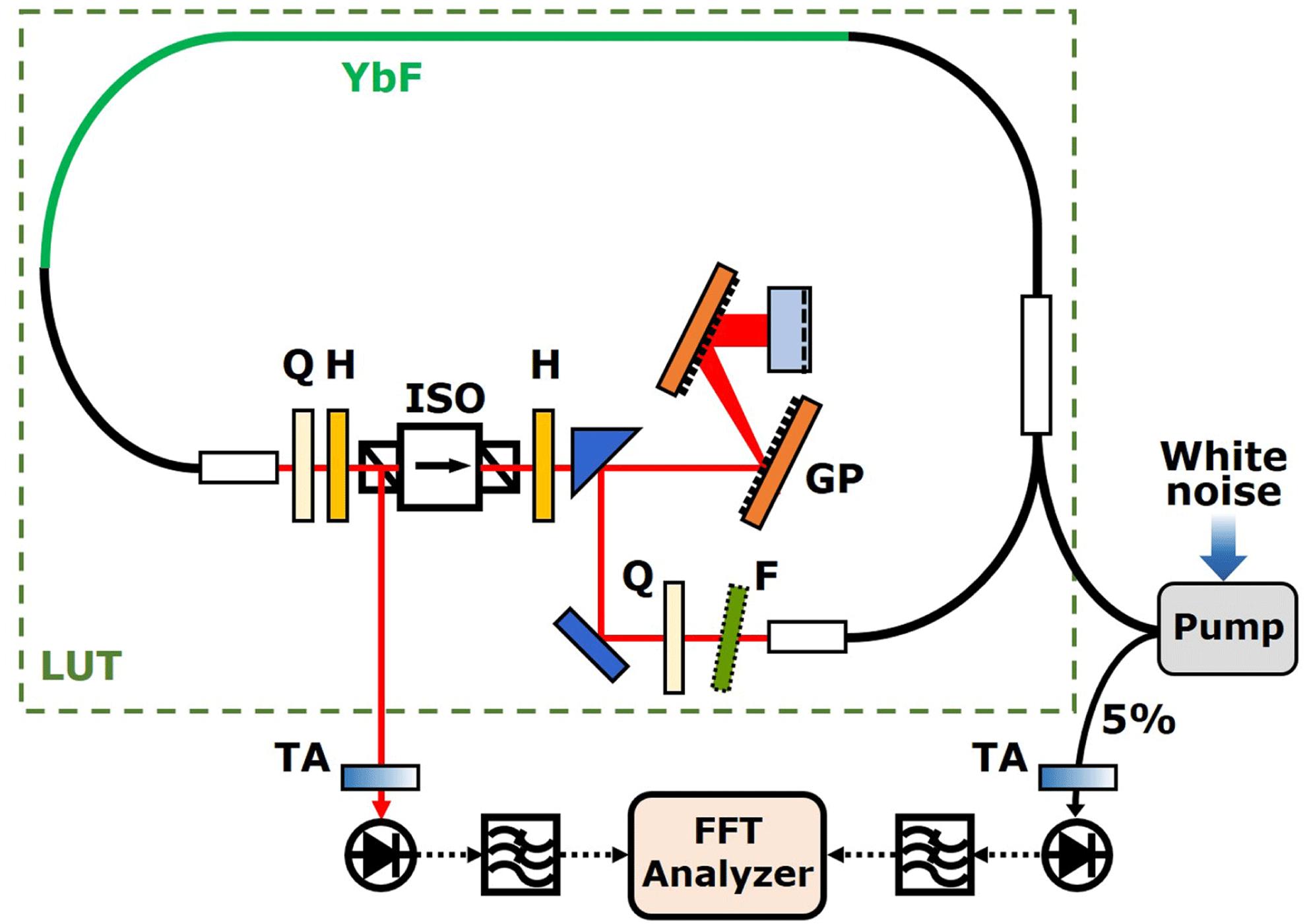
Fig. 1. Configuration of the RIN transfer function characterization system. YbF, ytterbium-doped fiber; Q, quarter waveplate; H, half waveplate; ISO, isolator; F, band-pass filter; GP, grating pair; LUT, laser under test; TA, tunable attenuator.
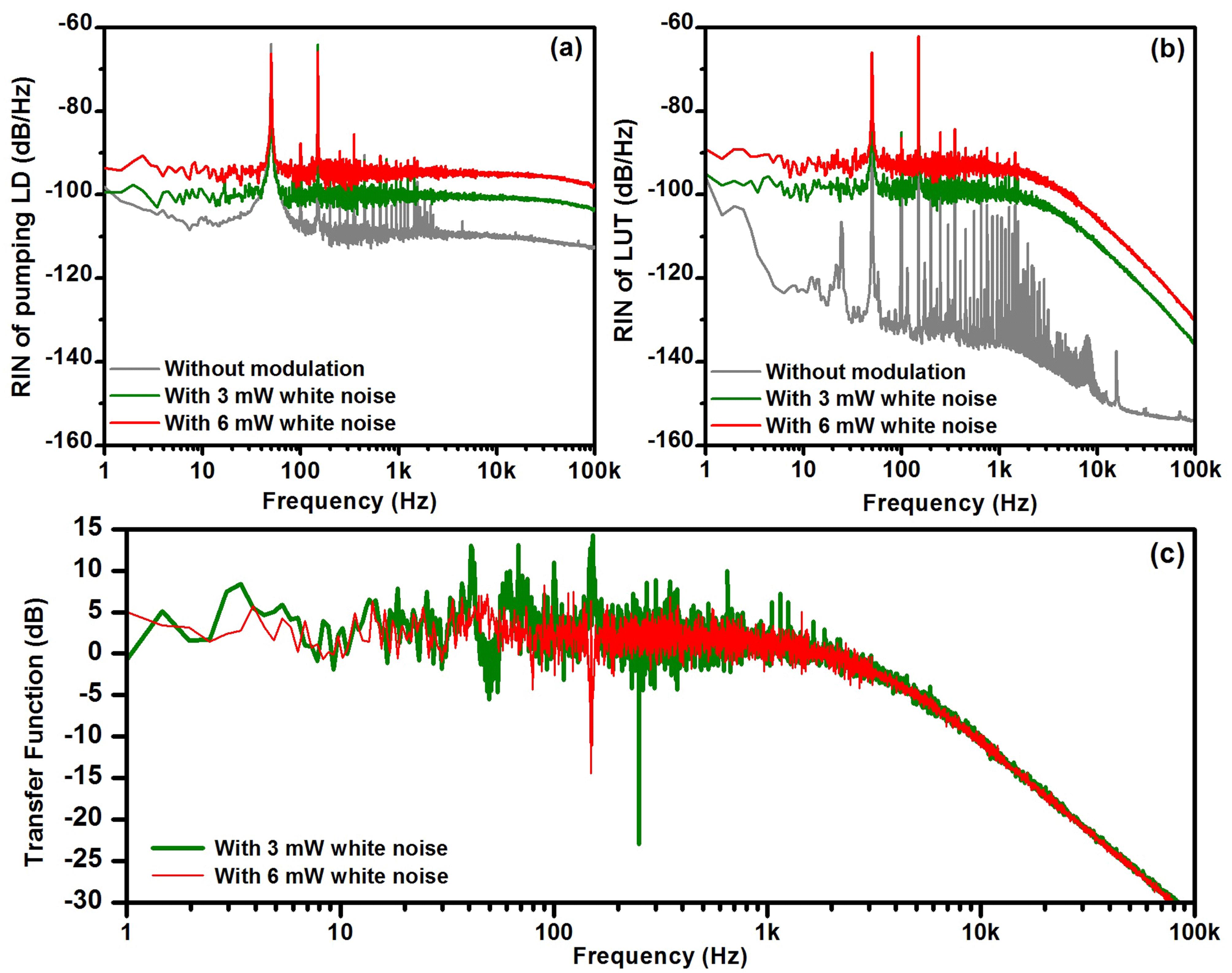
Fig. 2. (a) RIN of the pump LD with (red and green) and without (gray) white noise modulation. (b) RIN of the LUT with (red and green) and without (gray) white noise modulation. (c) Transfer function of the RIN measured by applying 3 mW (green) and 6 mW (red) white noise modulation.
Fig. 3. Transfer function curves of the RIN at (a) $+0.004~\text{ps}^{2}$ , with (red) and without (black) filter; (b) $+0.007~\text{ps}^{2}$ , with (pink) and without (blue) filter; (c) $-0.001~\text{ps}^{2}$ , with (orange) and without (green) filter; (d) $-0.012~\text{ps}^{2}$ , with (salmon) and without (purple) filter. SS, passive self-similar; AS, amplifier similariton; SP, stretched pulse; SOL, soliton. Insets: optical spectra of corresponding mode-locking regimes.
Fig. 4. Configuration of the timing jitter transfer function characterization system. REF, reference laser; DC, dispersion compensation system; BOC, balanced optical cross-correlation system; PI, proportional–integral controller.
Fig. 5. Transfer function curves of the timing jitter (a) at $-0.001~\text{ps}^{2}$ , with (orange) and without (green) filter and (b) for various levels of dispersion with filter.


Set citation alerts for the article
Please enter your email address

© Copyright 2018-2021 | Chinese Laser Press. All Rights Reserved 沪ICP备15018463号-20