• Chinese Optics Letters
  • Vol. 15, Issue 3, 030012 (2017)
Giovanni Milione1、*, Ting Wang1, Jing Han2, and Lianfa Bai2
Author Affiliations
  • 1Optical Networking and Sensing Department, NEC Laboratories America, Inc., Princeton, NJ 08540, USA
  • 2School of Electronic Engineering and Optoelectronic Technology, Nanjing University of Science and Technology, Nanjing 210094, China
  • show less
    DOI: 10.3788/COL201715.030012 Cite this Article Set citation alerts
    Giovanni Milione, Ting Wang, Jing Han, Lianfa Bai. Remotely sensing an object’s rotational orientation using the orbital angular momentum of light (Invited Paper)[J]. Chinese Optics Letters, 2017, 15(3): 030012 Copy Citation Text show less
    Schematics of a Gaussian light beam that is partially obstructed by an object that has a rotational orientation (ϕo) and theoretically calculated spiral spectra and phase differences of the partially obstructed Gaussian light beam’s constituent OAM modes as described in the text. The spiral spectra are normalized with respect to the sum of the powers of OAM modes from ℓ=−10 to ℓ=+10. The phase differences are relative to the phase of the ℓ=0 OAM mode.
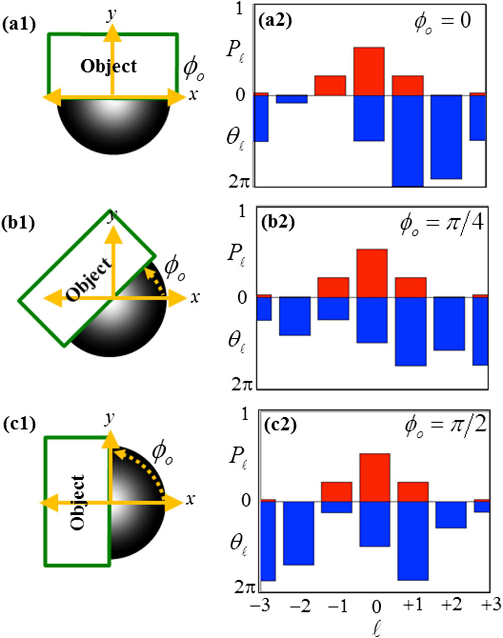
    Fig. 1. Schematics of a Gaussian light beam that is partially obstructed by an object that has a rotational orientation (ϕo) and theoretically calculated spiral spectra and phase differences of the partially obstructed Gaussian light beam’s constituent OAM modes as described in the text. The spiral spectra are normalized with respect to the sum of the powers of OAM modes from =10 to =+10. The phase differences are relative to the phase of the =0 OAM mode.
    Experimental setup as described in the text.
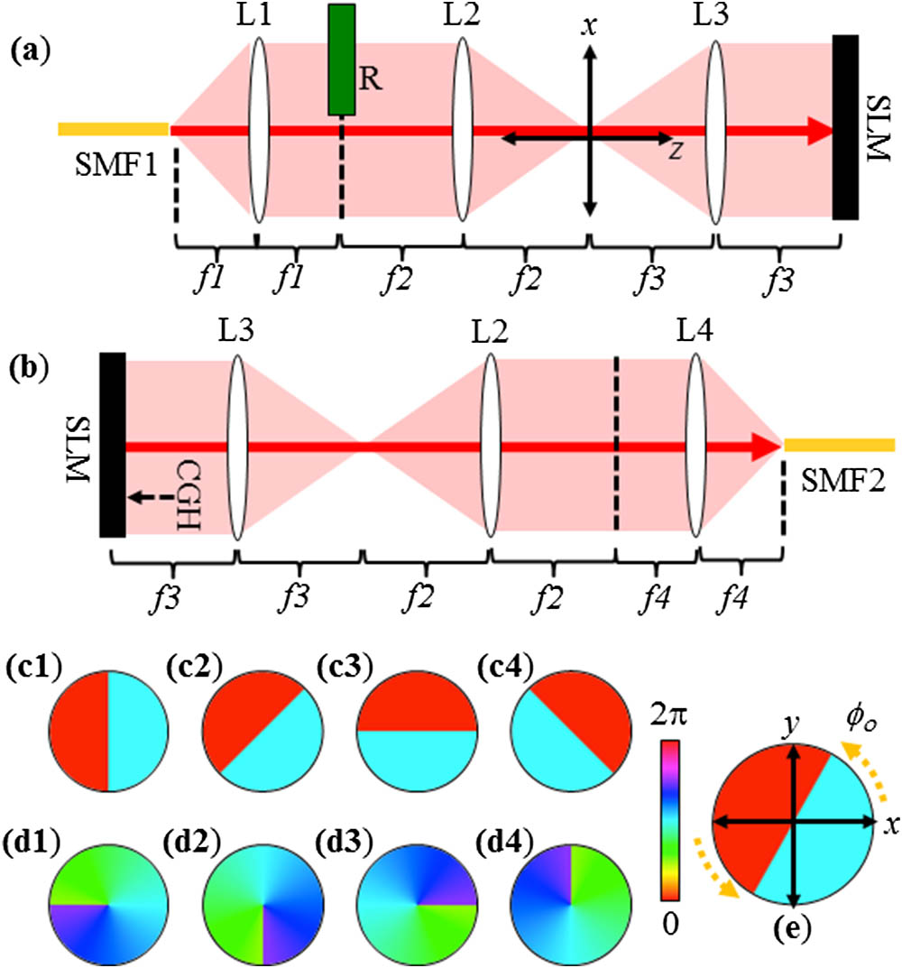
    Fig. 2. Experimental setup as described in the text.
    Measured phase differences (θ) between the ℓ=−1 and ℓ=+1 OAM modes of the partially obstructed Gaussian light beam as a function of the rotation angle (ϕo) as described in the text. Circles represent measured values. Solid lines represent theoretically calculated values. Note that the error bars are smaller than the markers.
    Fig. 3. Measured phase differences (θ) between the =1 and =+1 OAM modes of the partially obstructed Gaussian light beam as a function of the rotation angle (ϕo) as described in the text. Circles represent measured values. Solid lines represent theoretically calculated values. Note that the error bars are smaller than the markers.
    Measured phase differences (θ) between the ℓ=0 and ℓ=+1 OAM modes of the partially obstructed Gaussian light beam as a function of the rotation angle (ϕo) as described in the text. Circles represent measured values. Solid lines represent theoretically calculated values. Note that the error bars are smaller than the markers.
    Fig. 4. Measured phase differences (θ) between the =0 and =+1 OAM modes of the partially obstructed Gaussian light beam as a function of the rotation angle (ϕo) as described in the text. Circles represent measured values. Solid lines represent theoretically calculated values. Note that the error bars are smaller than the markers.
    Measured phase differences (θ) between the ℓ=−1 and ℓ=+1 OAM modes of the partially obstructed Gaussian light beam for three varying positions of R’s edge with respect to the light beam’s center as described in the text. Circles represent measured values. Solid lines represent theoretically calculated values. Note that the error bars are smaller than the markers.
    Fig. 5. Measured phase differences (θ) between the =1 and =+1 OAM modes of the partially obstructed Gaussian light beam for three varying positions of R’s edge with respect to the light beam’s center as described in the text. Circles represent measured values. Solid lines represent theoretically calculated values. Note that the error bars are smaller than the markers.
    Giovanni Milione, Ting Wang, Jing Han, Lianfa Bai. Remotely sensing an object’s rotational orientation using the orbital angular momentum of light (Invited Paper)[J]. Chinese Optics Letters, 2017, 15(3): 030012
    Download Citation