Longbo Xu, Shijie Liu, Rihong Zhu, You Zhou, Jie Chen, "Absolute surface form measurement of flat optics based on oblique incidence method," Chin. Opt. Lett. 16, 101201 (2018)
Copy Citation Text
In this Letter, a test method based on oblique incidence is practically implemented in the interferometric measurement process. Three sets of wavefront data are achieved through cavity interference measurement with a Fizeau interferometer and one oblique incidence measurement. An iterative algorithm is applied to retrieve the absolute surface shape of the test flat. By adding two sets of measurements, the absolute surface error of the interferometer’s reference flat can be obtained. The new method can not only calibrate the reference flat error of interferometer, but also provide the absolute measurement method for high precision optical components applied in high power laser systems.
With the development of the optoelectronic technique, super-smooth flat mirrors are widely used in optical systems like the high-end optical lithography system[1], astronomical telescope[2], and inertial confinement fusion[3]. The high accuracy requirement prompts the development of components processing to a kind of extreme direction. Therefore, a step forward in optical interferometric testing is also required. The existing typical absolute measurement methods include the 3-flat test, even and odd functions, N-rotation measurement, and iterative algorithm. The 3-flat test method only gets one-dimensional data each time[4–6]. The even and odd functions measurement method is limited by the optics diameter and the measurement steps are complex[7,8]. The N-rotation measurement method is also limited by the optical diameter[9,10]. Moreover, for large aperture systems, it is very difficult to frequently dismantle the transmitted flat when the above methods are implemented. For the absolute method based on an iterative algorithm, since three flats have to exchange their positions, it is difficult to measure the large aperture optics[11–13]. To overcome the disadvantages of the above methods, the skip-flat test method with several variations has been proposed. Vannoni proposed an absolute measurement method based on oblique incidence[14]. Only three measurement steps are required. The absolute surface form with high precision can be obtained with a designed iteration algorithm. Therefore, it could potentially be a very good method to measure the absolute shape of the large aperture flat applied in the high-precision interferometers, high-power laser systems, and space optics systems. But he only analyzed and deduced the method theoretically, and did not attempt to analyze the factors that affect the absolute measurement in practice. Lin et al. proposed an absolute surface metrology by rotational averaging in oblique incidence for the X-ray mirrors[15], but they only analyzed the number of rotations on the measurement accuracy, and more rotations of the reflective reference flat are required. Han et al. proposed a Zernike polynomial decomposition based on the skip flat test[16], and the defect of the method is that only low-frequency components of the sample can be retrieved. However, as far as we know, the oblique incidence absolute measurement with an iterative algorithm has not been practically implemented in the reported literature. Therefore, the real validity and effectiveness of this method is still unknown in the optical measurement community.
In this Letter, the absolute measurement method based on oblique incidence is implemented in the interferometric measurement process. Three sets of wavefront data are obtained through cavity interference measurement with a Fizeau interferometer and one oblique incidence measurement. An iterative algorithm is applied to retrieve the absolute surface shape of the test flat (TF). By adding two sets of measurements, the absolute surface error of the interferometer’s reference flat (RF) can be obtained. The new method can not only calibrate the reference flat error of large aperture interferometer, but also provide the absolute measurement method for large optical components applied in high power laser systems.
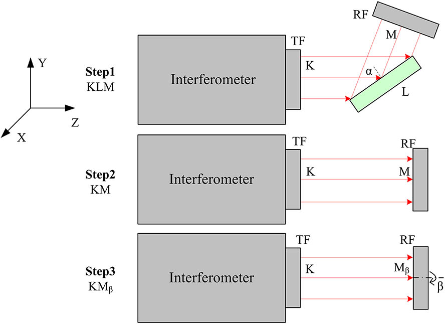
The principle of the absolute surface measurement method based on oblique incidence is shown in Fig. 1, in which a Fizeau interferometer is equipped with a transmitted flat (named by ) and a reference flat (named by ). Three measurement steps are involved, as illustrated in Fig. 1. (1) A tested surface (named by ) is inserted between and at a certain incidence angle . The first measurement of wavefront error KLM can be obtained. (2) After the tested surface is removed, the cavity error composed of and is measured, which results in the second measurement of wavefront error KM. (3) After rotating the reference flat at a certain angle , the cavity error composed of both and is measured again, which results in the third measurement of wavefront error . The content of the three measurements can be expressed by Eqs. (1) to (3): where , , and are the measured wavefront errors illustrated in steps 1, 2, and 3 in Fig. 1, respectively. Under the coordinates defined in Fig. 1, represents the surface form error of transmission flat , represents the surface form error of the reflected flat under the oblique incidence layout, represents the surface form error of the reflected flat M under normal incidence, and represents the surface form error of the reflected flat under normal incidence after being rotated by . From Eqs. (1) and (2), we can get Eq. (4):
Sign up for Chinese Optics Letters TOC. Get the latest issue of Chinese Optics Letters delivered right to you!Sign up now
Figure 1.Principle of the absolute measurement method based on oblique incidence.
The figure map of can be divided into two separate contributions: a rotationally invariant part and a rotation dependent part. The rotationally invariant part is also mirror invariant, so it is automatically cancelled in Eq. (4) by the difference . What remains is due to the rotation dependent part only. Such a part can be retrieved by the iterative algorithm, with KM and as inputs.
To recover the absolute surface form of the tested part , a retrieved algorithm, as shown in Fig. 2, is applied. A set of trial surfaces and is first generated by a random matrix. Then KM and can be calculated by Eqs. (2) and (3). Compared with the experimental measurement of surfaces and , the residual surfaces of and can be obtained. If the root mean square (RMS) of and is greater than a certain threshold, i.e., , then a new matrix of and is generated and a new loop will restart. Otherwise, the surfaces and will be output, which can be used to calculate the absolute surface of at oblique incidence. The absolute surface of at normal incidence can be calculated by the interpolation of surface .
Figure 2.Retrieval algorithms for absolute surface measurement.
From the above, by only rotating with a certain angle and iterative algorithm, while rotation invariant errors on and are still present, the oblique map of can be retrieved with sub-nanometric RMS accuracy[14]. We can get the absolute surface shape of L to be measured, and the result does not include the surface error of the interferometer’s TF and RF.
If we want to completely get the absolute surface error of the TF (K) of the interferometer, we need to use the TF to measure the again, which has been absolutely measured. After deducting the surface error of the from the measurement result, the absolute surface error of the TF can be completely obtained, and it is clear that the diameter of the is exactly the same as the diameter of the TF. When we get the absolute surface error of TF, we can also measure the absolute surface error of RF (M).
The selection of the oblique incidence angle is first determined by the measurement beam size and the horizontal size of tested part . It means that the oblique incidence angle should be big enough to make the projection area of the measurement beam cover the effective aperture of the tested part. Moreover, as the incidence angle increases, the error induced by the double cubic interpolation algorithm will increase[17], as shown in Fig. 3. We generated three circular synthetic surfaces (, , and ) using 36 random Zernike polynomials with zero piston and tilt; the diameter of the synthetic data is 100 mm, and the lateral resolution is set to the existing 4 inch interferometer. The peak-valley (PV) of and is 21.52 nm, the PV of is 61.04, 19.10, and 12.89 nm. As is seen in Fig. 3, the relative interpolation error PV is less than 1.0% when the incidence angle is 30°.
Figure 3.Relative interpolation error PV due to the oblique incidence angle for different flatnesses of .
The rotation angle is another critical parameter during the absolute measurement process. Here, the PV and RMS of are 19.10 and 3.36 nm. Different rotation angles are made to calculate the RMS of the residual error between the restored surface and the original surface of . When the rotation angle varies from 20° to 70°, the RMS of the residual error shows several peaks, as shown in Fig. 4. The maximum residual error is bigger than 1 nm. As long as these peaks are avoided, the RMS of the residual error will be small enough. For example, the RMS value can be as small as 0.35 nm at a rotation angle of 55°. The control precision for the rotation angle is also analyzed. As shown in Fig. 5, the RMS of the residual error oscillates with the increase of measurement times when the control precision is 0.01°, 0.1°, 0.5°, and 1°, respectively. When the rotation angle error is less than 0.1°, the repeatability becomes stable and the mechanical structure is easy to design and manufacture.
Figure 4.Residual error (RMS) as a function of rotation angle.
The absolute measurement experiment is implemented. As shown in Fig. 6, a 4D Fizcam 2000 interferometer is used for the surface error measurement. Three flats with flatness of about are employed in order to test the effectiveness of the absolute measurement method. A five-dimensional adjustment rotating device is used to rotate the flat at a precision of 0.1°. The rotating device also has an XYZ tip-tilt mount enabling precision translation in the , , and axes and a tip-tilt adjustment for laser interferometer measurements. The setup is placed in an ISO 6-level clean room with a temperature of and a humidity of 45%. The incident angle and rotation angle are 30° and 50°, respectively.
Figure 6.Experimental setup for the absolute measurement.
To verify the effectiveness and validity of the new method, two other methods, including the N-rotation measurement method and relative measurement method, are also implemented in the experiment. The surface measurement results are shown in Fig. 7, where Figs. 7(a), 7(b), and 7(c) are the results by the three methods, respectively. It is seen that the distributions of the surface form measured with the three methods show a good similarity. Because the surface error from the flat K has been removed, both Figs. 7(a) and 7(b) have very close PV values, which are a little smaller than that of Fig. 7(c) as shown in Table 1.
Parameter
Oblique incidence method
N-rotation measurement method
Relative measurement method
PV (nm)
18.98
15.82
24.05
RMS (nm)
3.92
3.25
5.77
MSF (nm)
0.5
0.3
0.4
GRMS (nm/cm)
4.5
3.5
6.1
Table 1. Summary of the Surface Form Measurement Results
Figure 7.Surface form measurement results with three different methods: (a) oblique incidence method, (b) N-rotation method, and (c) relative measurement method.
Figure 8.Gradient of the surface form measurement results with three different methods: (a) oblique incidence method, (b) N-rotation method, and (c) relative measurement method.
Figure 9.Mid-spatial frequency error of the surface form measurement results with three different methods: (a) oblique incidence method, (b) N-rotation method, and (c) relative measurement method.
Gradient and mid-spatial frequency error are also two important parameters to describe the performance of flat optics. Based on the calculation algorithm in Ref. [18], the gradient and mid-spatial frequency error are also calculated using the surface form measurement results with the three different methods, as shown in Fig. 8 and Fig. 9, respectively. As is seen in Table 1, the results from the two absolute methods still show a good agreement, and have a deviation from the results by the relative measurement method, including the error of flat .
In summary, the absolute measurement method based on the oblique incidence and an iterative algorithm is practically implemented. Algorithmic simulation shows that the relative interpolation error PV is less than 1.0% when the incidence angle is 30°. Determination of the rotation angle should be careful in order to avoid the local maximum error. Moreover, the rotation angle error should be controlled to be less than 0.1°. Based on the above conditions, the error in the iterative algorithm can be less than 0.5 nm in principle. The experiment shows that the results obtained by the oblique incidence method are basically the same as those by the N-rotation method. Furthermore, the new method can improve the measurement accuracy of the surface form compared to the relative measurement. In the future, we will further apply this method to the absolute measurement of larger aperture interferometer standard flats and the wavefront error of the meter size rectangular optics.
Longbo Xu, Shijie Liu, Rihong Zhu, You Zhou, Jie Chen, "Absolute surface form measurement of flat optics based on oblique incidence method," Chin. Opt. Lett. 16, 101201 (2018)