1Beijing Key Laboratory for Precision Optoelectronic Measurement Instrument and Technology, School of Optics and Photonics, Beijing Institute of Technology, Beijing 100081, China
2Shenzhen Institutes of Advanced Technology, Chinese Academy of Sciences, Shenzhen 518055, China
3Key Laboratory of Terahertz Optoelectronics, Ministry of Education, Beijing Key Laboratory for Terahertz Spectroscopy and Imaging, and Beijing Advanced Innovation Center for Imaging Technology, Department of Physics, Capital Normal University, Beijing 100048, China
To make further understanding of terahertz (THz) wave generation from liquid water, we study THz wave emission from water lines of different diameters. The water line with a smaller diameter generates a stronger THz electric field for the diameters from 0.2 mm to 0.5 mm. The THz electric field strength and polarity change with the relative position between the incident laser and water line. Moreover, the THz energy has an optimal radiation angle of about 60°. A two-dimensional dipole array model is introduced to illustrate the phenomenon. Our observations contribute to optimizing the scheme of the liquid THz source.
Various types of solid-state and gas-state terahertz (THz) sources have been proposed and developed in recent years, such as photoconductive antennas[1–3], gas plasma[4–11], nonlinear optical crystals[12–15], and metal films[16–19]. However, since liquid water has strong absorption in the THz frequency band, it has been widely believed to be almost impossible to exploit liquid water as a THz source. Liquid has no damage threshold due to its fluidity; the generation of electromagnetic waves from liquids has been becoming a research focus. Liquid water has been successfully applied as a source of various electromagnetic waves, such as high harmonics[20,21], white light[22], and X ray[23]. Very recent reports have shown the possibility that THz radiation can be produced by ultrafast laser-induced filament in liquids[24]. In order to minimize the absorption of THz by liquid water, the researchers designed a water film with the thickness of a sub-millimeter and focused the monochromatic femtosecond laser into the water film, thus observing effective generation of THz waves[25]. In the following studies, the water film scheme was further explored and optimized[26], and THz radiation was obtained by irradiating the water film with the two-color laser fields[27]. Even though the feasibility of using liquid water as a THz source has been demonstrated, the mechanism has not been sufficiently explained, and the generation efficiency needs to be highly improved. In addition to liquid water, different types of polar liquids in a flat jet have also been used for highly efficient THz wave generation, and the dependences on liquid and laser parameters were systematically investigated[28]. More recently, our group proposed to use a water line instead of a water film as a THz source. It has been demonstrated that a more efficient THz wave can be generated from a water line than from a water film[29].
In this Letter, we will further study the THz wave generation mechanism from a liquid water line and propose an optimized scheme of a water line to produce efficient THz waves. The water lines of different diameters were employed to generate THz waves. We observed that the water line with a diameter of 0.2 mm works best, while the water line with a diameter of 0.5 mm can only emit very weak signals. Furthermore, the THz signal strength is highly dependent on the relative position between the incident laser and the water column. Then, we found two maxima during the movement of the water lines, and their polarities are opposite. Moreover, the angular distribution of the emitted THz energy from the water lines of different diameters was also observed. The two-dimensional dipole array model was adopted to simulate the THz generation process from the laser induced plasma. Specially, the absorption effect of water was further considered to analyze the THz wave propagation process in the water line. The simulation results are in good agreement with the experimental observations.
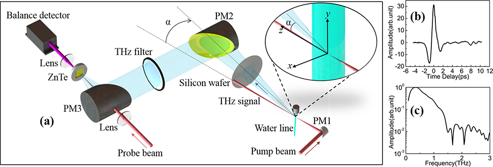
A schematic diagram of the experimental setup is shown in Fig. 1. The laser pulse is delivered by a regenerative -polarized Ti:sapphire amplifier (Spitfire, Spectra Physics) with a Gaussian pulse duration of 50 fs, a center wavelength of 800 nm, a repetition rate of 1 kHz, and an energy per pulse of 2 mJ. The laser beam is split into two beams by a quartz plate. One is a pump beam and the other is a probe beam. The round-hole nozzles of different diameters (0.2 mm to 0.5 mm diameter) were employed to create water lines in this study.
Sign up for Chinese Optics Letters TOC. Get the latest issue of Chinese Optics Letters delivered right to you!Sign up now
Figure 1.(a) Schematic of the experiment system. PM1–PM3 are off-axis PMs. The inset illustrates the geometry of the interaction between the laser and the water line. In subsequent experiments, the water line moves primarily along the axis. (b) and (c) THz time-domain and frequency-domain amplitudes generated by 0.2 mm water line at and at .
The pump beam is focused into the water line by an off-axis parabolic mirror (PM1) with a focal length of 1 in., and it creates a plasma inside the water line. The forward THz energy is collimated and refocused by a pair of off-axis PMs (PM2, PM3) with an effective focal length of 2 in. The residual pump laser was blocked by a silicon wafer (thickness of 0.5 mm) and a long pass THz filter (Tydex). The probe beam is focused by a convex lens after passing through the time delay stage and is focused onto the ZnTe crystal together with the THz wave. Standard electro-optical sampling with a 3-mm-thick ZnTe crystal is used to detect the THz field. In the experiment, we investigated the THz electric field dependence on the relative position between the water line and the incident laser. We moved the water line horizontally, which is perpendicular to the propagation direction of the pump laser. As shown in Fig. 1(a), the angle between the direction of THz signal detection and the direction of the pump optical axis is . In this measurement, the angle was set to be zero. The THz time-domain and frequency-domain amplitudes generated by a 0.2 mm water line at and are shown in Figs. 1(b) and 1(c).
Figure 2(a) shows the detected THz peak electric field intensity when moving the nozzles with different apertures. In this experiment, the pulse duration remained consistent for different diameters. As the water line moves horizontally (in the positive and negative directions along the axis), the magnitude and polarity of the THz electric field change. The THz time-domain waveforms at the positions with maximum peak amplitude in different diameter water lines are shown in Figs. 2(b)–2(e). For water lines of 0.2 mm, 0.3 mm, 0.4 mm, and 0.5 mm, the maximum values of the THz signal appear at , , , and , respectively. For each water line at the positive and negative optimal positions, the maximum amplitudes of the THz time-domain signals are substantially equal, but the polarities are opposite. As the water line diameter increases from 0.2 mm to 0.5 mm, the generated THz signal becomes smaller.
Figure 2.(a) THz peak electric field intensity as a function of position with the water line diameter of 0.2 mm, 0.3 mm, 0.4 mm, and 0.5 mm, respectively. (b)–(e) THz time-domain waveforms at the positions with maximum peak amplitude in different diameter water lines.
For describing the generation and propagation process of THz waves in the water line, a theoretical model is proposed. In this model, the recorded THz radiation from laser induced plasma is considered as a superposition of emission by a two-dimensional dipole array. First, the spherical dipole model is used to characterize a single dipole in one direction. For each one of the dipoles in the array, the generated THz electric field strength in the far field can be given by where is the current amplitude phasor, is the length of the electric dipole, is the wave number, is the wave frequency, is the dielectric constant of free space, is the distance from the observation point to the origin point, and is the angle between the observation point and the spherical coordinate axis.
The intensity of the array dipole can be expressed as follows: where is the number of dipoles during simulation, and is distance between two adjacent dipoles.
Figure 3(a) shows the diagram of the relative position between the water line and the laser for three typical positions, where the THz peak electric field strength is maximum, minimum, and almost zero, respectively. The black dotted line connecting Figs. 3(a) and 3(b) indicates the direction in which off-axis PM2 in the detection system receives the THz signal. The schematic diagrams of a two-dimensional dipole array and the electric field of a single dipole are also shown in Fig. 3(a). During the movement of the water line along the axis, the position of the pump laser on the surface of the water line changes. The refraction angel of the pump laser as it enters the water line changes. Therefore, the angle between the direction of the receiving THz electric field and the spherical coordinate axis in the dipole model can be given by the following formula: where is the distance that the water line moves laterally, is the water line radius, and is the refractive index of water.
Figure 3.(a) Relative positional relationship between the water line and the laser induced plasma (including the two-dimensional dipole array diagram) during the movement of the water line. (b) Normalized THz peak electric field strength as a function of the position for the water line of 0.2 mm; the experimental and simulation results are shown by dots and line.
The most important factor affecting THz propagation in the water line is the absorption of the THz wave by water, with the absorption coefficient of at 1 THz[22]. This effect has also been considered in the THz generation from water film[25]. As the water line moves, the thickness of the water layer absorbing the THz wave also changes, resulting in different attenuations of the THz electric fields. The transmission rate of THz electric field can be expressed as follows: where and are functions of the plasma center coordinates with respect to x, , . By combining Eqs. (1) and (3), the detected THz electric field intensity after water attenuation can be obtained. Then, the detected THz electric field can be formulated as where is the initial THz intensity generated by the laser induced plasma, and A is the transmission rate of the THz wave in water line.
For the instance of the 0.2 mm diameter water line, the experimental and simulation results for the normalized THz peak electric field strength distribution as a function of the water line x position are shown in Fig. 3(b). When the laser axis is at the center of the water line, the detected THz signal is almost zero. Moreover, as the water line moves (), the THz electric field amplitude first increases and then decreases, and the maximum amplitude appears at . In addition, due to the refraction of the pump laser on the surface of the water line, the movement of the water line changes the direction of the central axis of the plasma. As shown in Fig. 3(a), at , the center of off-axis PM2 faces the negative electric field side of the dipole analogic electric field. In contrast, at , the center of off-axis PM2 faces the positive electric field side of the dipole analogic electric field. Therefore, the polarities of the THz electric field are reversed.
The main reason why the 0.2 mm water line generates the highest THz signal among 0.2–0.5 mm water lines is the absorption of the THz wave by water. When the diameter of the water line becomes larger, the THz wave generated inside the water line needs to transmit through a thicker water layer into the air. According to Eq. (4), for the water lines with diameters from 0.2 mm to 0.5 mm, we can conclude that the 0.2 mm water line has the maximum transmission rate and can achieve the highest THz radiation.
To fully characterize the property of the THz wave emission from water line, we measured the angular distribution of THz energy, which is recorded by a Golay cell (Tydex). The collection portion is installed on a platform that can be rotated around the water line to detect the THz energy at an angle (positive: anti-clockwise) with respect to the laser incident direction. The water line stayed at the optimal position for this measurement. That is, the 0.2 mm water line stayed at , the 0.3 mm water line stayed at , and the 0.4 mm water line stayed at , respectively.
The experimental results of the angular distribution of THz energy are shown in Fig 4. For the 0.2 mm diameter water line, the THz energy observed in the direction of the pump optical axis () is not the strongest. At the angle of about , the maximum THz energy was detected. According to Eq. (1), the initial THz radiation just from the plasma has an angular distribution inside the water line. The strongest THz energy is radiated perpendicularly to the laser direction in the water line. Then, the radiated THz wave propagates through the water layer and refracts into the air. The propagation distance in the water line is the other main reason that determines the THz energy observed by the detector. For the observation angel of about 60°, the combined effect of the initial THz radiation direction from the plasma and the corresponding propagation distance in the water line works best, which contributes to the highest THz energy. Moreover, the optimal detection angles for different water lines are slightly different, because the initial THz radiation distribution and the subsequent water absorption influence have a small difference for the water lines with different diameters.
Figure 4.Experimental results of the angular distribution of THz energy produced by the water lines with three different diameters (0.2 mm, 0.3 mm, 0.4 mm) at the optimal positions.
In summary, we propose an effective solution for THz wave emission from liquid water. The experimental results show that the strength and polarity of the generated THz electric field change with the relative position between the incident laser and water line. The performance of the water line with 0.2 mm diameter is better than that of the 0.3 mm, 0.4 mm, and 0.5 mm diameter water lines. We used the two-dimensional dipole array model to explain this phenomenon, and the simulation results are quite consistent with the experimental data. Moreover, the angular distributions of THz energies generated by water lines of different diameters were demonstrated. In order to receive the maximum THz signal, it is necessary to ensure the receiving direction of the detecting system at an angle of about 60° with respect to the optical axis of the pump laser. Our study could contribute to further understanding and optimizing the THz wave emission from liquid water.
[15] K. Kang, L. L. Zhang, T. Wu, K. Li, C. L. Zhang. Chin. Opt. Lett., 16, 110401(2018).
[16] F. Kadlec, P. Kuzel, J. L. Coutaz. Joint International Conference on Infrared & Millimeter Waves & International Conference on Terahertz Electronics, 455(2004).
[17] G. H. Welsh, N. T. Hunt, K. Wynne. Phys. Rev. Lett., 98, 026803(2007).