
Yi Liu, Ming Chen, Pingyuan Liang, Taoyun Zhou, Shan Qiu, Yun Cheng. OCT-based partial data-carrying subcarriers precoding and ISFA-enabled DMT-VLC system[J]. Chinese Optics Letters, 2023, 21(2): 020602
- Chinese Optics Letters
- Vol. 21, Issue 2, 020602 (2023)
Abstract
Keywords
1. Introduction
Recently, visible light communication (VLC) is perceived as a promising solution for the further 6G communication networks, because of its inherent advantages, such as a large license-free spectrum, high confidentiality, and low electromagnetic pollution[1]. Compared with light-emitting diodes (LEDs)-enabled VLC, application scenarios of VLC based on laser diode (LD) can easily achieve high-speed and long-distance signal transmissions owing to its inherent large bandwidth of LDs[2]. To further improve the data rate, the discrete multi-tone (DMT) modulation technique with high spectral efficiency (SE) has been widely investigated in both real-time and offline digital signal processing (DSP) approaches[3–5]. Unfortunately, the overall bit error ratio (BER) or signal-to-noise ratio (SNR) performance may be seriously degraded by the various impairments in the DMT VLC transmission system, such as digital-analog converter (DAC)/analog-digital converter (ADC)-induced clock tone leakage (CTL)[6], imperfect optoelectronic devices-induced nonlinear effect, and serious low-pass-like decline[7]. In the literature, one classic and effective scheme named the adaptive modulation technique is widely used in VLC, which can equalize the subcarrier (SC) SNR to a uniform level to boost the system’s capacity[8]. In Ref. [9], an adaptive partition precoding scheme is experimentally verified, which is used to unlock the ability to control the SNR of each data-carrying SC. Another simplified scheme named the pre-emphasis technique based on electronic circuits is proposed in Ref. [10], which can effectively compensate for power fading on the high-frequency SCs in the transmission system. However, the adaptive loaded DMT and pre-emphasis technique are all channel-dependent and require the channel state information (CSI) with the reverse link, which is complex and time consuming. In Ref. [11], the authors proposed and experimentally demonstrated a static adaptive modulation method coupled with the forward error correction (FEC) technique to compensate for the unbalanced impairments. However, this technique restricted their application for scenarios that have a time-varying channel.
Nowadays, a channel-independent precoding scheme is seen as another effective way to compensate for unbalanced impairments. The precoding/decoding based on seven common precoding matrices are realized by multiplying the transmitted/received mapped DMT symbols by its precoding matrix/reverse matrix, respectively[12]. In this work, the computational complexity of seven precoding techniques has been theoretically analyzed and compared as well. According to this paper, when the amplitudes of the elements in precoding matrices are all set to an equal number, even SNR distribution can be achieved for overall data-carrying SCs after precoding. In Ref. [13], it concluded that the orthogonal circular matrix transform (OCT)-based precoding scheme can achieve better SNR equalization and BER performance than the discrete Fourier transform (DFT)-based precoding scheme in the bandwidth-limited DMT VLC system. Some other precoding matrices have been also used in terms of equalizing the SNRs over data-carrying SCs, such as the Walsh–Hadamard transform (WHT) matrix[14], constant amplitude zero autocorrelation sequence (CAZAC) matrix[15], and discrete Hartley transform (DHT) matrix[16]. The precoding technique is also applied to enhance the peak-to-average power ratio (PAPR) performance, owing to the improvement of the autocorrelation performance of signal symbols[17], and to mitigate nonlinear distortions induced by electrical/optical devices.
All of the data-carrying SCs in DMT symbols are used in the processing of precoding in the above-mentioned works, and we call this method full data-carrying SC precoding (FDSP). Since the Hermitian symmetry (HS) constraint is required for the inverse fast Fourier transform (IFFT) to obtain the real-valued DMT signal, the number of data-carrying SCs is generally not an integer power of two. In this case, the precoding techniques cannot be implemented with the corresponding fast Fourier transform (FFT)-based fast algorithms. Moreover, when a large number of SCs are employed for data delivery, the FDSP exhibits high complexity from a hardware implementation point of view. To deal with this issue, the multi-band OCT-based precoding technique was proposed[18]. A block precoding (BL) scheme, in which the data-carrying SCs are divided into several groups, and the number of data-carrying SCs is an integer power of two in each group, was proposed in Refs. [19,20]. However, the difference in equalized SNRs is relatively large among these sub-bands or groups. Compared to the uniform modulation scheme, these methods need to adopt different modulation formats according to the SNRs of sub-bands or groups, which become more complex for the implementation of the precoded DMT-VLC systems.
Sign up for Chinese Optics Letters TOC. Get the latest issue of Chinese Optics Letters delivered right to you!Sign up now
In this Letter, an improved precoding method based on OCT is proposed and experimentally verified in the DMT VLC transmission system. Partial data-carrying SCs are selected for precoding, which owns a significant reduction in required multiplication and addition operations. In addition, the intra-symbol frequency average (ISFA) technique is employed to enhance the overall system performance. The rest of this Letter is structured as follows. The operation principle of the partial data-carrying SCs precoding (PDSP) technique and its computational complexity are analyzed in Section 2. The experimental setup and verification are described in Sections 3 and 4, respectively. The conclusion is finally summarized in Section 5.
2. Operation Principle
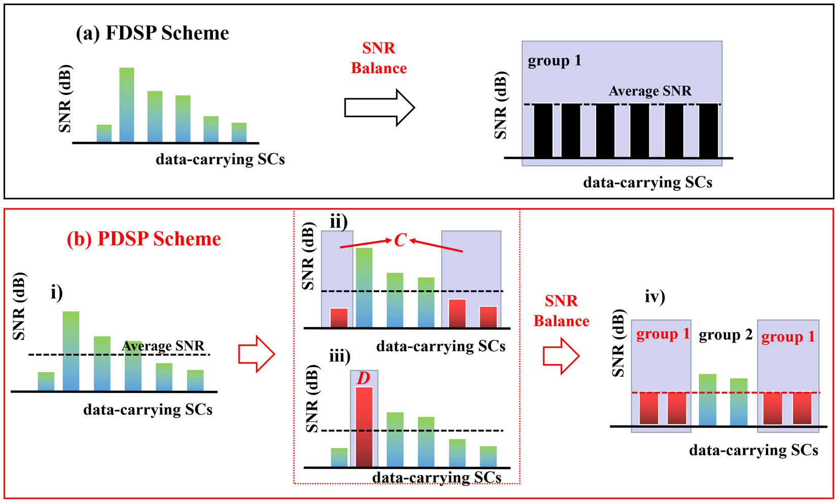
As we know, the frequency responses of optical/electrical devices such as LD and electronic amplifier (EA) are imperfect, resulting in low SNR performance for some low- and high-frequency data-carrying SCs[21]. In the FDSP case, all of the data-carrying SCs are regarded as one group and used for performing precoding, as shown in Fig. 1(a). As mentioned above, the number of data-carrying SCs is usually not an integer power of two since the HS constraint is required for real-valued DMT signal generation. Thus, the hardware implementation of the FDSP is a big challenge when a large FFT size is applied. The implementation of the PDSP can be summarized as the following steps: (i) compare the SNRs of data-carrying SCs with the average SNR; (ii) select C data-carrying SCs at high/low frequency whose SNRs are lower than average SNR; (iii) select D data-carrying SCs at low frequency with highest SNRs; (iv) partial data-carrying SCs in group 1 (C + D) with a number of two on both sides are selected for SNR balance enabled by the precoding, while no precoding is performed for the left data-carrying SCs in group 2, as shown in Fig. 1(b). In this case, the implementation complexity can be significantly reduced with the proposed PDSP scheme.
![]()
Figure 1.Schematic diagram of the proposed FDSP scheme in the DMT transmission system.
2.1. OCT-based PDSP scheme
At the transmitter, assume that and data-carrying SCs are selected for precoding for FDSP and PDSP schemes, respectively. The corresponding mapped symbols can be expressed as and , where and can be an integer power of two. Here, we use and to denote the transpose operation and normalization factor, respectively. Thus, by multiplying the OCT-based precoding matrix , the PDSP precoded signal symbol can be written as
In our PDSP method, the OCT-based precoding matrix is constructed by employing the Zadoff–Chu (ZC) sequence with a different length parameter . When is even or odd, the th element in the ZC sequence, , can be expressed as the following in Eq. (2) or (3), respectively:
It should be noted that the elements in the th row of are the cyclic shift of the ZC sequence by elements. After the -point IFFT operation, the transmitted PDSP DMT signal without cyclic prefix (CP)/cyclic suffix (CS) is given by[22]
2.2. SNR balance
At the receiver, without considering the inter-carrier interference (ICI) and inter-symbol interference (ISI), after FFT operation, the received PDSP signal symbol can be depicted by
Note that the channel transfer matrix, , is a diagonal matrix that can be expressed as diag, and the frequency response of the th SC is . Similarly, the noise on the th SC is denoted by , which obeys Gaussian distribution with variance and zero mean. The corresponding noise vector in the frequency domain is expressed as .
Assuming that accurate channel estimation and ideal channel equalization are employed, the finally recovered PDSP DMT symbol, , can be written as
According to Eqs. (8) and (9), we can see that the SNR value on each precoded data-carrying SC is equalized to and for the PDSP and FDSP schemes, respectively, when the absolute values of elements in the matrix [see Eq. (1)] are equal. In contrast, the SC SNR of the DMT signal without using precoding is proportional to the amplitude response.
2.3. Complexity comparison
The computational complexities of FDSP/PSDP schemes are analyzed and listed in Table 1. As mentioned above, the number of data-carrying SCs () is not an integer power of two in an OCT-based FDSP scheme, and the required real-valued multiplication and addition operations may be very resource-intensive. However, the OCT precoding technique can be implemented with its fast algorithm based on FFT[23] when the number of precoded data-carrying SCs () is an integer power of two. Therefore, the computational complexity of the fast algorithm for the OCT-based PDSP scheme can be significantly reduced.
| Precoding Scheme | According to Eq. ( | FFT-based Fast Algorithm[ | ||
|---|---|---|---|---|
| Real Mult. | Real Add. | Real Mult. | Real Add. | |
| FDSP | 4M2 | 4M2 − 2M | – | – |
| PDSP | 4L2 | 4L2 − 2L | L log2(L) + 5L + 4 | 3L log2(L) + L + 4 |
Table 1. FDSP/PDSP Computational Complexity Analysis
3. Experimental Setup
The experimental setup of the OCT-based PDSP scheme for the DMT VLC transmission system is illustrated in Fig. 2(a). At the transmitter, the digital DMT signal is generated offline with DSP approaches in MATLAB. Firstly, the pseudo-random binary sequence (PRBS) is generated. Then, the QAM modulation scheme is applied to PRBS mapping. Partial high-frequency SCs and direct current SCs are filled with zeros. Different from the conventional DMT, the OCT-based PDSP scheme is used after mapping. It should be noted that the effective number of data-carrying SCs for both the FDSP and PDSP schemes is 384. But, the number of data-carrying SCs, which are used for precoding for FDSP and PDSP schemes, is 384 and 256, respectively. After HS operation, 1024-point IFFT is employed to offer a real-valued PDSP DMT signal. The CP/CS is added to eliminate ISI. Besides, one training sequence is inserted in front of each precoded DMT frame to facilitate timing synchronization and zero-forcing channel equalization[24]. Finally, the DMT signal is digitally clipped to combat the DAC-induced quantization noise[25] and reduce the PAPR. The analog electrical precoded DMT signals are uploaded to a commercial Tektronix arbitrary waveform generator (AWG, AWG7122C). The sampling rate of AWG and resolution for DAC are 2.5 GSa/s and 10 bits, respectively. There, the bandwidth of the DMT signal is constantly equal to . The corresponding gross bit rate is 3.75 Gb/s [(2.5 × 400 × 384 × 4)/(1024 × 400)], and the net bit rate is 3.52 Gb/s {(2.5 × 400 × 384 × 4)/[(1024 + 64) × 400]}. The bandwidth of the DMT signal is , and the corresponding SE of the DMT signal is 3.52/0.094 = 3.75 (b/s)/Hz. It should be mentioned that the average signal power of the conventional DMT signal and the FDSP/PDSP DMT signals remains the same in our experiment. The converted signal is suppressed by a low-pass filter (LPF) with a bandwidth of . A Mini-Circuits EA (model ZX60-14012L-S+) is utilized to amplify the electrical DMT signal and then drive the LD (PL450B) via a bias-tee. The central wavelength of the optical DMT signal is 450 nm. To make the LD work at the linear range, different bias currents are discussed in the following section. The output optical power versus bias current is given in Fig. 2(b).
![]()
Figure 2.(a) Experimental setup. Insets are (b) the output power versus bias current and (c) the spectrum of the received DMT signal.
At the receiver, after 1.9 m free-space transmission, the optical precoded DMT signals are detected by a photodiode (PD) and captured by a digital storage oscilloscope (DSO, Lecroy Wavemaster 820-Zi-A). The sampling rate of the DSO and resolution for ADC are 5 GSa/s and 8 bits, respectively. The sampled data are post-processed with the receiver DSP. Its flow includes the time-domain CTL compensation (TD-CLC) technique, TS-based symbol timing synchronization, CP/CS removal, FFT, ISFA-enhanced least-square channel estimation, one-tap frequency-domain equalization, decoding, and symbol de-mapping. Finally, BER is calculated for evaluating system performance. The spectrum of the received DMT signal is shown in Fig. 2(c). Some key parameters of the precoded DMT frame are indicated in Table 2.
| Parameter | Value | Unit | |
|---|---|---|---|
| FDSP | PDSP | ||
| Modulation format | 16QAM | – | |
| IFFT/FFT size | 1024 | Points | |
| Data SCs | 384 | 384 | – |
| Precoded data SCs | 384 | 256 | – |
| CP/CS length | 32 | – | |
| TS per frame | 1 | – | |
| DMT symbols per frame | 400 | – | |
| Clipping ratio (CR) | 12 | dB | |
| Bandwidth | 0.94 | GHz | |
| Net bit rate | 3.52 | Gb/s | |
| Spectral efficiency | 3.75 | (b/s)/Hz | |
Table 2. Some Key Parameters of the Precoded DMT Frame
4. Results and Discussion
To identify the optimal IFFT size for the DMT VLC system, the conventional DMT signal is first sent by the transmitter. After 1.9 m free-space transmission, BER and SNR performances as a function of bias current are shown in Figs. 3 and 4, respectively. It should be noted that the SNR mentioned in this paragraph refers to the average SNR of all data-carrying SCs. We can see clearly that the SNR and BER performances are improved with the increase in IFFT size. Since the light intensity is controlled by a bias current, a high bias current can raise the power of the signal to improve the SNR but also cause nonlinear distortion. When the bias current becomes larger than 100 mA, the SNR and BER performance begins to degrade due to the nonlinear impairments. The optimum performance is observed when the bias current is fixed at 100 mA. It shows clearly that there is about 13.5 dB SNR improvement when the IFFT increases from 64 to 1024. The main reason is that the DMT signal with a large IFFT size has less side-lobe power leakage and thus is less sensitive to narrow filtering effects. As IFFT size increases from 1024 to 4096, both the SNR and BER performance improvements are trivial.
![]()
Figure 3.SNR performance versus bias current for different IFFT sizes.
![]()
Figure 4.BER performance versus bias current for different IFFT sizes.
With the non-flat amplitude response for data SCs, high channel estimation accuracy may be achieved owing to the small SC spacing for large-size IFFT/FFT cases. By using the ISFA technique, the system noises on adjacent data-carrying SCs can be suppressed after the averaging operation. As a result, the accuracy of channel estimates can be further enhanced. The BER performances as a function of ISFA taps are given in Fig. 5. Here, ISFA taps mean the number of adjacent data-carrying SCs whose channel estimate is used for the averaging operation. As the bias current is set to 100 mA, the optimal ISFA taps for 64/128/256/512/1024/2048/4096 IFFT-size are 3/3/5/7/9/9/9, respectively. When the ISFA tap increases and reaches the corresponding optimal values, the BER performances are gradually improved for all different IFFT sizes, compared to the ISFA-free case (ISFA taps = 1). However, the channel estimation accuracy is gradually decreased when the ISFA taps are greater than their optimal taps. This fact is mainly due to the increased difference in frequency response over more adjacent data-carrying SCs. Considering the computational complexity and trivial performance gain, we set IFFT/FFT size and ISFA taps to 1024 and 9, respectively, in the following discussion.
![]()
Figure 5.BER performance versus number of ISFA taps for different IFFT sizes.
When the bias current is fixed at 100 mA, the estimated SC SNR curves for the received conventional DMT signals are presented in Fig. 6. As shown in Fig. 6(a), there is about 5 dB SNR degradation for the 256th SC, which is caused by the DSO clock leakage. We use a time-domain averaging method[6] to compensate for the impairment, and the estimated SC SNR after clock leakage compensation is given in Fig. 6(b). In the following content, the clock leakage is compensated, unless otherwise stated.
![]()
Figure 6.SC SNR for conventional DMT signals: (a) without TD-CLC; (b) with TD-CLC.
The estimated SC SNRs for three kinds of DMT signals are shown in Fig. 7. The SC SNR fluctuation is up to 19 dB for the conventional signal. The imperfect frequency response of the LD and EA are the main reasons for low SNRs on the low-frequency SCs. The degraded SNR on the high-frequency SCs is mainly caused by the bandwidth limitations of the AWG and LD. By using FDSP or PDSP schemes, the SNR values on the precoded SCs are well balanced. Unlike the FDSP scheme, only 256 data-carrying SCs, with indices of 1st–161st and 290th–384th, are used for the proposed PDSP scheme. Therefore, we can observe that the SNR value of the precoded SCs with the PDSP scheme is slightly lower than that of the FDSP scheme, but higher SNR performance on the middle data-carrying SCs with indices from the 162nd to 289th is achieved with the PDSP scheme.
![]()
Figure 7.Estimated SC SNR for three kinds of DMT signal schemes.
When the bias current is fixed at 100 mA, the recovered 16-QAM constellations are plotted in Fig. 8. Compared to the conventional DMT technique, the FDSP and PDSP schemes make the constellation points more distinct, even though their error vector magnitude (EVM) performances are very similar. Moreover, the EVM performance can be improved by ISFA with optimal taps.
![]()
Figure 8.Recovered 16QAM constellations and their EVM values: (a) conventional without ISFA; (b) conventional with ISFA; (c) FDSP without ISFA; (d) FDSP with ISFA; (e) PDSP without ISFA; (f) PDSP with ISFA.
The offline BER performance as a function of bias current is also measured, and the corresponding curves are plotted in Fig. 9. When the setting value of the bias current is far away from the optimal value of 100 mA, a slight improvement in BER performance can be observed for the FDSP and PDSP schemes, compared to the conventional DMT scheme. It is mainly attributed to the nonlinear distortions induced by the LD, which deteriorate the SNR performances. In this case, the precoding technique may not improve or even degrade the BER performance at low SNRs[12]. By using ISFA, the BER improvement is more obvious for FDSP and PDSP schemes, compared to the conventional one. The BER performance with FDSP/PDSP combined with ISFA can be improved by up to more than an order of magnitude. In addition, the proposed PDSP scheme can obtain a similar BER performance to the FDSP scheme, but with lower computational complexity. Therefore, the PDSP scheme may be more suitable for the unbalanced impairments compensation in the band-limited DMT-VLC transmission system.
![]()
Figure 9.BER performance versus bias current for different DMT signals.
5. Conclusion
We proposed a low-complexity OCT-based PDSP scheme to combat the unbalanced impairments of DMT-VLC transmission systems. Experimental results show that with the 3.52 Gb/s DMT signal after 1.9 m free-space transmission the BER performance can be improved by up to an order of magnitude with the proposed PDSP scheme and can further be enhanced when the ISFA algorithm with optimal taps is employed. Compared with the conventional FDSP scheme, the PDSP obtains a similar BER performance and can significantly reduce the implementation complexity.
References
[1] P. H. Pathak, X. Feng, P. Hu, P. Mohapatra. Visible light communication, networking and sensing: a survey, potential and challenges. IEEE Commun. Surv. Tutor., 17, 2047(2015).
[2] N. Chi, Y. Zhou, Y. Wei, F. Hu. Visible light communication in 6G: advances, challenges, and prospect. IEEE Veh. Technol. Mag., 15, 93(2020).
[3] Z. Y. Xu, W. Q. Niu, J. Y. Shi, N. Chi. Nonlinear coded nonuniform superposition QAM by trellis-coding for MISO system in visible light communication. Chin. Opt. Lett., 20, 042501(2022).
[4] C. H. Yeh, L. Y. Liu, C. W. Chow. Real-time white-light phospher-LED visible light communication (VLC) with compact size. Opt. Express., 21, 26192(2013).
[5] J. Vucic, C. Kottke, S. Nerreter, K.-D. Langer, J. W. Walewski. 513 Mbit/s visible light communications link based on DMT-modulation of a white LED. J. Light. Technol., 28, 3512(2010).
[6] M. Chen, L. Zhang, K. Bai, F. Li, G. Liu, H. Zhou, Q. Chen. 100-Gb/s DMT transmission for short-reach optical interconnect with DAC clock leakage compensation. IEEE Photon. Technol. Lett., 31, 1791(2019).
[7] X. Huang, Z. Wang, J. Shi, Y. Wang, N. Chi. 1.6 Gbit/s phosphorescent white LED based VLC transmission using a cascaded pre-equalization circuit and a different outputs PIN receiver. Opt. Express, 23, 22034(2015).
[8] P. S. Chow, J. Cioff, J. A. C. Bingham. A practical discrete multitons transceivers loading algorithm for data transmission over spectrally shaped channel. IEEE Trans. Commun., 43, 773(1995).
[9] X. Chen, Z. Feng, M. Tang, S. Fu, D. Liu. Performance enhanced DDO-OFDM system with adaptive partitioned precoding and single sideband modulation. Opt. Express, 25, 23093(2017).
[10] Y. F. Liu, Y. C. Chang, C. W. Chow, C. H. Yeh. Equalization and pre-distorted schemes for increasing data rate in in-door visible light communication system. Optical Fiber Communications Conference and Exhibition, JW.A83(2011).
[11] Z. Cao, G. Wen, F. Li, Q. Shu, J. Yu, L. Chen. Unbalanced impairments compensation for low cost direct detection OFDM-PON systems. Opt. Commun., 310, 35(2014).
[12] M. Chen, L. Wang, D. S. Xi, L. Zhang, H. Zhou, Q. H. Chen. Comparison of different precoding techniques for unbalanced impairments compensation in short-reach DMT transmission system. J. Light. Technol., 38, 6202(2020).
[13] Y. Hong, X. Guan, L. Chen, J. Zhao. Experimental demonstration of an OCT-based precoding scheme for visible light communication. Optical Fiber Communications Conference and Exhibition, M3A.6(2016).
[14] R. Deng, J. He, M. Chen, Y. Zhou. Experimental demonstration of a real-time gigabit OFDM-VLC system with a cost-efficient precoding scheme. Opt. Commun., 423, 69(2018).
[15] Z. Feng, Q. Wu, M. Tang, R. Lin, R. Wang, L. Deng, S. Fu, P. P. Shum, D. Liu. Dispersion-tolerant DDO-OFDM system and simplified adaptive modulation scheme using CAZAC precoding. J. Light. Technol., 34, 2743(2016).
[16] X. Ouyang, J. Jin, G. Jin, W. Zhang. Low complexity discrete Hartley transform precoded OFDM for peak power reduction. Electron. Lett., 48, 90(2012).
[17] T. Jiang, M. Tang, R. Lin, Z. Feng, X. Chen, L. Deng, S. Fu, X. Li, W. Liu, D. Liu. Investigation of DC-biased optical OFDM with precoding matrix for visible light communications: theory, simulations, and experiments. IEEE Photon. J., 10, 7906916(2018).
[18] Y. Hong, J. Xu, L. K. Chen. Experimental investigation of multi-band OCT precoding for OFDM-based visible light communications. Opt. Express, 25, 12908(2017).
[19] L. Wang, M. Chen, G. Chen, A. Deng, H. Zhou, Y. Liu, Y. Cheng. Fast WHT-based block precoding for DMT transmission. Asia Communications and Photonics Conference, W4B.6(2021).
[20] F. Li, X. Xiao, X. Li, Z. Dong. Real-time demonstration of DMT-based DDO-OFDM transmission and reception at 50 Gb/s. European Conference on Optical Communication, 1(2013).
[21] K. Q. Wu, J. He, J. Ma, Y. R. Wei. A BIPCM scheme based on OCT precoding for a 256-QAM OFDM-VLC system. IEEE Photonics Technol. Lett., 30, 1866(2018).
[22] J. Armstrong. OFDM for optical communications. J. Light. Technol., 27, 189(2009).
[23] J. Zhao, Y. Hong, L. Chen. Discrete-circulant-transform spread OFDM for bandwidth-limited VLC systems. J. Light. Technol., 37, 5340(2019).
[24] Y. Liu, J. He, M. Chen, Y. Q. Xiao, Y. Cheng. 64APSK constellation scheme for short-reach DMT with ISDD enabled SFO compensation. Opt. Commun., 467, 125689(2020).
[25] M. Chen, J. He, Q. Fan, Z. Dong, L. Chen. Experimental demonstration of real-time high-level QAM-encoded direct-detection optical OFDM systems. J. Light. Technol., 33, 4632(2015).

Set citation alerts for the article
Please enter your email address
© Copyright 2018-2021 | Chinese Laser Press. All Rights Reserved 沪ICP备15018463号-20