
Guang-Ming Guo, Lin Zhu, Bo-Yang Xing. Density distribution characteristics of fluid inside vortex in supersonic mixing layer [J]. Acta Physica Sinica, 2020, 69(14): 144701-1
- Acta Physica Sinica
- Vol. 69, Issue 14, 144701-1 (2020)
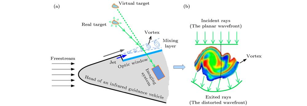
Fig. 1. (a) Schematic of aero-optic effects of an infrared guidance vehicle; (b) wavefront distortion caused by a vortex.

Fig. 2. The vorticity contour of a supersonic mixing layer simulated by LES.
Fig. 3. Process of establishing an elliptic model for the vortex boundary: (a) Two vortices; (b) LCS; (c) elliptic model of vortex boundary
Fig. 4. Schematic of calculating position coordinates of a vortex core.
Fig. 5. Method of representing fluid density distribution inside a vortex based on its boundary and core location.
Fig. 6. (a)The supersonic mixing layer with Mc = 0.5; (b) Vortex A; (c) Vortex B; (d) Vortex C.
Fig. 7. Density distribution of fluid inside three vortices: (a) Density distribution of fluid inside Vortex A along the flow direction (x -axis); (b) density distribution of fluid inside Vortex A along the longitudinal direction (y -axis); (c) density distribution of fluid inside Vortex B along the flow direction (x -axis); (d) density distribution of fluid inside Vortex B along the longitudinal direction (y -axis); (e) density distribution of fluid inside Vortex C along the flow direction (x -axis); (f) density distribution of fluid inside Vortex C along the longitudinal direction (y -axis).
Fig. 8. Supersonic mixing layers with different compressibilities
Fig. 9. Density distribution of fluid inside two vortices in the supersonic mixing layers with different compressibilities.
Fig. 10. (a) Supersonic mixing layer with Mc = 0.3; (b) two adjacent vortices during their merging process.
Fig. 11. Variation curve of the fluid density inside the vortex a and b during their merging process.
Fig. 12. Variation of fluid density at several characteristic points during their merging process.
Fig. 13. (a) The supersonic mixing layer with different inflow density of its upper and lower layers; (b) density distribution of fluid inside the vortex along the longitudinal direction (y -axis); (c) density distribution of fluid inside the vortex along the flow direction (x -axis).
| ||||||||||||||||||||||||||||||
Table 1. Inflow parameters of three supersonic mixing layers.
| ||||||||||||||||||||||||||
Table 2.
Geometric parameters of three vortices with different sizes.
不同空间尺寸涡结构的几何参数
| ||||||||||||||||||||
Table 3.
Geometric parameters of two vortices in the fields with different compressibilities.
不同压缩性超声速混合层涡结构的几何参数


Set citation alerts for the article
Please enter your email address

© Copyright 2018-2021 | Chinese Laser Press. All Rights Reserved 沪ICP备15018463号-20