
Bo Dai, Zhengmeng Zhou, Yan Long, Mingliang Pan, Zeyuan Song, Dawei Zhang, "Multi-focused droplet lens array inspired by movable-type printing technology," Chin. Opt. Lett. 19, 102201 (2021)
- Chinese Optics Letters
- Vol. 19, Issue 10, 102201 (2021)
Abstract
1. Introduction
Lens arrays are fundamental optics that have a variety of functional features including light collection from a wide angle, light homogenization, and anti-reflection[
Highly packed lens arrays can be rapidly produced by the thermal reflow technique, in which an array of polymer cylinders is melted into a spherical cap[
Recently, droplet lenses have attracted lots of research interests because of their simplicity in manufacturing, low cost, and special features in functions[
Sign up for Chinese Optics Letters TOC. Get the latest issue of Chinese Optics Letters delivered right to you!Sign up now
In most lens arrays, individual lenses have a uniform focal length. The intrinsic nature of the lens array limits the depth of field for 3D imaging and 3D display. Only a few lens arrays with lenses of different focal lengths have been proposed by using the thermal reflow technique and the hot embossing technique[
In this Letter, we demonstrate a movable-type lens array, in which individual droplet lenses of specific focal length could be flexibly reorganized based on a certain combination. The scheme is inspired by the movable-type printing technology that was first, to the best of our knowledge, invented in China around 1040 and is an efficient way to use a combination of movable-type pieces to reproduce documents. In the proposed lens array, groups of movable lenses, which have different focal lengths, were assembled to form a lens array, and the lens array can achieve a large focus range for imaging.
2. Fabrication of the Multi-Focus Droplet Lens Array
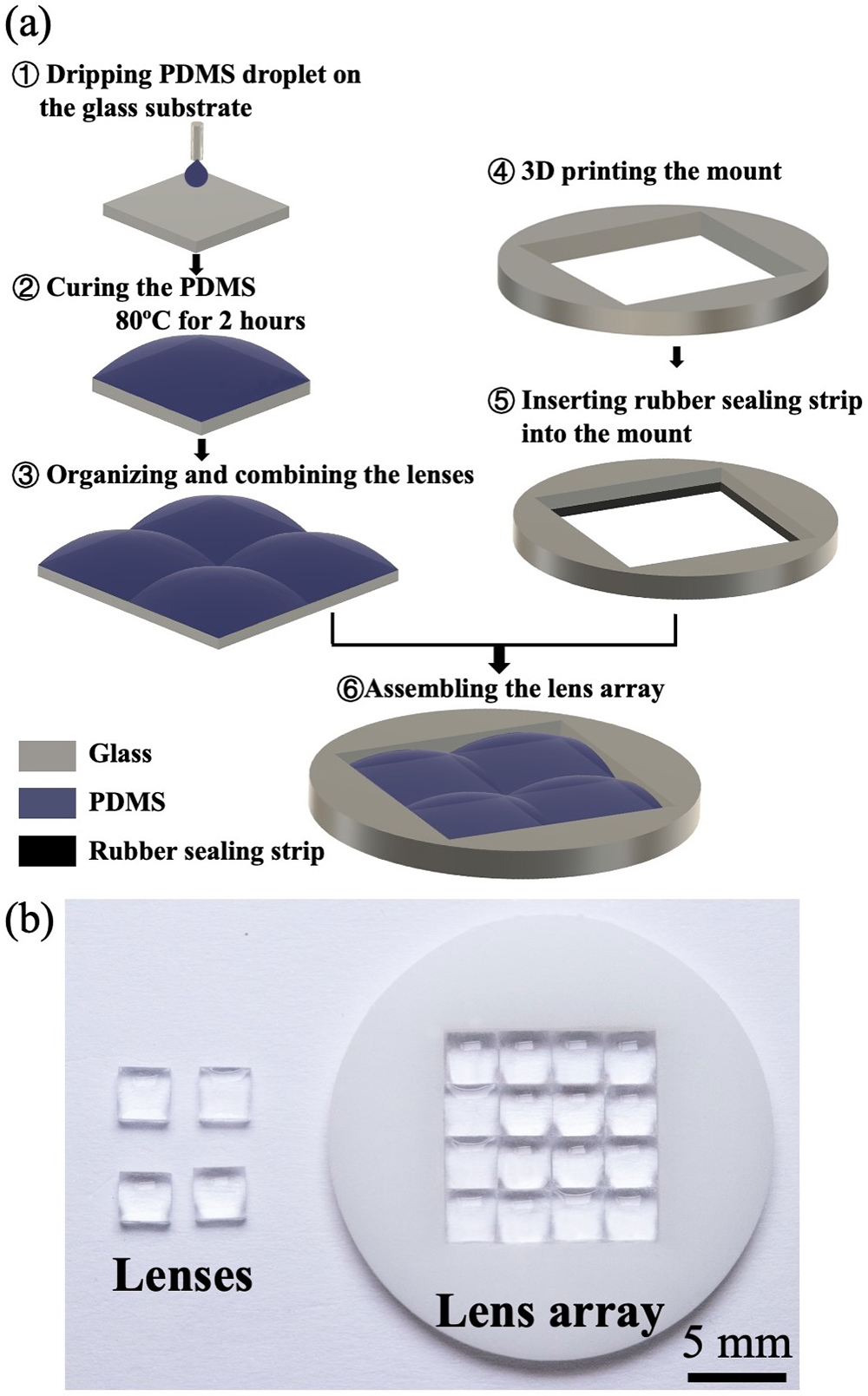
Figure 1(a) illustrates the fabrication procedure of the proposed scheme. The individual lenses are firstly prepared by dripping liquid-state polydimethylsiloxane (PDMS) with a mixture ratio 10:1 (weight ratio between elastomer and curing agent) (refractive index: 1.403) onto a square glass substrate, which is used as pedestals to hold the PDMS. The gravitational force makes the PDMS spread over the pedestals, while the surface tension prevents the PDMS from sliding off the pedestals and curves the surface of the PDMS remaining on the pedestals, forming lenses. The curvature of the PDMS surface is proportional to the amount of the droplets. Then, the lenses are solidified at 80°C for 2 h.
![]()
Figure 1.(a) Fabrication procedure of the lens array. (b) Photos of the fabricated lenses and the assembled lens array.
Meanwhile, a mount is designed and produced by 3D printing. A hollow square whose size matches that of the group of the lenses is designed in the center of the mount. The perimeter of the hollow square is embedded with a square silicone ring. After that, a group of prepared lenses, just like the movable-type pieces in the movable-type printing system, are selected and flexibly organized according to a certain combination based on their optical properties. Finally, the lenses are installed into the mount. The whole assembly is tightly bound together by the silicone ring in the mount to form a lens array.
The spare fabricated lenses and the assembled lens array are shown in Fig. 1(b). The size of each lens is 3 mm
3. Optical Performance of the Multi-Focus Droplet Lens Array
The focusing capability of the lenses is investigated. Figure 2(a) illustrates the experimental setup for focal length measurement. A white-light source is used to generate a collimated light beam. A
![]()
Figure 2.(a) Experimental setup for measuring the image distance. (b) Captured image of the focused light spots. (c) The relation between the image distance and the mass of the droplet.
The droplet lenses are fabricated on a square substrate. They can be easily assembled in the lens array with extremely high packing density. The droplet lenses in the square shape are astigmatic lenses. The meridians have different curvatures and periodically vary. The model of the droplet lenses is depicted in Fig. 3. The lens is on a square pedestal with the length of
![]()
Figure 3.Model of the square droplet lens.
Then, the difference in curvature of the meridians is investigated. In the theoretical calculation, the height of the lens,
In the experimental measurement, the side views of the lenses, corresponding to different angles of the meridians,
![]()
Figure 4.(a) Side views of the lenses. (b) The relation between the curvature and the angle of the meridians. Solid line and dashed line represent the theoretical results.
Two lenses made of PDMS of different mass,
4. Imaging Performance of the Multi-Focus Droplet Lens Array
Furthermore, the imaging performance of the lenses is evaluated. Figure 5(a) illustrates the imaging system. The white-light collimated beam directly illuminates the object. The USAF 1961 resolution target is used in the testing. A microlens array is placed behind the object. The CCD camera equipped with a telecentric lens is used to record the images. The distance between the object and the lens array changes, while the distance between the lens array and the CCD camera is fixed. Four identical lenses, which are made of 3.6 mg PDMS droplets, are installed in the lens array. Figure 5(b) shows the images captured by the imaging system when the object distance is
![]()
Figure 5.(a) Experimental setup of the imaging system. (b) The images captured by the lens array equipped with four identical lenses.
The lens array can be flexibly equipped with the lenses from a combination of desired focal lengths. Figure 6(a) depicts the principle of the imaging by using the lenses of a variety of focal lengths. The image distance is fixed, while the object distance varies according to the optical property of the lenses. The lenses of a variety of focal lengths are capable of collecting the images of the object at different distances. With the change of the object distance, magnification is different. The image of the object collected by the lenses of short focal lengths can get high magnification.
![]()
Figure 6.(a) Schematic diagram of imaging using the lens array equipped with different lenses. (b)–(e) The images captured by the lens array when the object is placed at different distances away from the lens array.
Figures 6(b)–6(e) demonstrate the images collected by a
5. Improvement Schemes of the Multi-Focus Droplet Lens Array
The square lenses are easy to put together to form a high-filling-factor lens array, but it also causes astigmatism aberration in imaging. To eliminate astigmatism aberration and improve imaging quality, two schemes can be adopted, as illustrated in Fig. 7. Scheme 1: each lens is formed on a round substrate. When dripping the droplet on a round substrate, the liquid spreads over the substrate and stops spreading when it reaches the edges of the substrate. The liquid gradually bulges into a spherical cap, and a spherical lens can be formed. The droplet lenses formed on the round substrate have no astigmatism aberration and can present good imaging quality[
![]()
Figure 7.Improvement of the lens array for eliminating astigmatism aberration in imaging. (a) Scheme 1: mounting and assembling round lenses together. (b) Scheme 2: assembling square lenses that are formed into a round shape and then cut into a square.
6. Conclusion
In conclusion, we have demonstrated a cost-efficient way for fabricating a high-filling-factor lens array, in which movable lenses can be flexibly reorganized according to a preferred combination. By using the lens array equipped with lenses of different focal lengths, the depth of field for imaging can be significantly extended. In future work, the optical performance of the individual lens, especially the imaging quality, could be improved by avoiding astigmatism aberration. Moreover, the size of the lenses can be reduced to the several-hundred-micrometer scale to enhance the resolving power in some advanced microscopic imaging applications[
References
[1] J. Tseng, Y. Chen, C. Pan, T. Wu, M. Chung. Application of optical film with micro-lens array on a solar concentrator. Sol. Energy, 85, 2167(2011).
[2] T. Zhu, J. Fu, F. Lin, M. Zhang, W. Wang, F. Wen, X. Zhang, R. Bu, J. Zhang, J. Zhu, J. Wang, H. Wang, X. Hou. Fabrication of diamond microlens arrays for monolithic imaging homogenizer. Diam. Relat. Mater., 80, 54(2017).
[3] X. Sang, X. Gao, X. Yu, S. Xing, Y. Li, Y. Wu. Interactive floating full-parallax digital three-dimensional light-field display based on wavefront recomposing. Opt. Express, 26, 8883(2018).
[4] P. Chou, J. Wu, S. Huang, C. Wang, Z. Qin, C. Huang, P.-Y. Hsieh, H.-H. Lee, T.-H. Lin, Y. Huang. Hybrid light field head-mounted display using time-multiplexed liquid crystal lens array for resolution enhancement. Opt. Express, 27, 1164(2019).
[5] Z. Zhang, J. Chang, H. Ren, K. Fan, D. Li. Snapshot imaging spectrometer based on a microlens array. Chin. Opt. Lett., 17, 011101(2019).
[6] S. Huang, M. Li, L. Shen, J. Qiu, Y. Zhou. Fabrication of high quality aspheric microlens array by dose-modulated lithography and surface thermal reflow. Opt. Laser Technol., 100, 298(2018).
[7] C. Dai, K. Agarwal, J.-H. Cho. Ion-induced localized nanoscale polymer reflow for three-dimensional self-assembly. ACS Nano, 12, 10251(2018).
[8] C. S. Lim, M. H. Hong, Y. Lin, Q. Xie, B. S. Luk’yangchuk. Microlens array fabrication by laser interference lithography for super-resolution surface nanopatterning. Appl. Phys. Lett., 89, 191125(2006).
[9] M. Li, Q. Yang, J. Yong, J. Liang, Y. Fang, H. Bian, X. Hou, F. Chen. Underwater superoleophobic and anti-oil microlens array prepared by combing femtosecond laser wet etching and direct writing techniques. Opt. Express, 27, 35903(2019).
[10] X. Liu, L. Yu, S. Yang, Q. Chen, L. Wang, S. Juodkazis, H. Sun. Optical nanofabrication of concave microlens arrays. Laser Photon. Rev., 13, 1800272(2019).
[11] T. Yang, H. Lin, B. Jia. Ultrafast direct laser writing of 2D materials for multifunctional photonics devices. Chin. Opt. Lett., 18, 023601(2020).
[12] Z. Hou, J. Cao, A. Li, H. Yang. Tunable protein microlens array. Chin. Opt. Lett., 17, 061702(2019).
[13] C. S. Lim, M. H. Hong, A. Senthil Kumar, M. Rahman, X. D. Liu. Fabrication of concave micro lens array using laser patterning and isotropic etching. Int. J. Mach. Tools Manuf., 46, 552(2006).
[14] H. Bian, Q. Yang, F. Chen, H. Liu, G. Du, Z. Deng, J. Si, F. Yun, X. Hou. Scalable shape-controlled fabrication of curved microstructures using a femtosecond laser wet-etching process. Mater. Sci. Eng. C, 33, 2795(2013).
[15] Y. Li, M. Hong. Parallel laser micro/nano-processing for functional device fabrication. Laser Photon. Rev., 14, 1900062(2020).
[16] M. H. Wu, C. Park, G. M. Whitesides. Fabrication of arrays of microlenses with controlled profiles using gray-scale microlens projection photolithography. Langmuir, 18, 9312(2002).
[17] Z. Zhang, C. Geng, Z. Hao, T. Wei, Q. Yan. Recent advancement on micro-/nano-spherical lens photolithography based on monolayer colloidal crystals. Adv. Colloid Interface Sci., 228, 105(2015).
[18] C. Jiang, X. Li, H. Tian, C. Wang, J. Shao, Y. Ding, L. Wang. Lateral flow through a parallel gap driven by surface hydrophilicity and liquid edge pinning for creating microlens array. ACS Appl. Mater. Interfaces, 6, 18450(2014).
[19] D. Zhang, Q. Xu, C. Fang, K. Wang, X. Wang, S. Zhuang, B. Dai. Fabrication of a microlens array with controlled curvature by thermally curving photosensitive gel film beneath microholes. ACS Appl. Mater. Interfaces, 9, 16604(2017).
[20] Q. Xu, B. Dai, Y. Huang, H. Wang, Z. Yang, K. Wang, S. Zhuang, D. Zhang. Fabrication of polymer microlens array with controllable focal length by modifying surface wettability. Opt. Express, 26, 4172(2018).
[21] Y.-L. Sung, J. Garan, Z. Hu, X. Shan, W.-C. Shih. Modeling the surface of fast-cured polymer droplet lenses for precision fabrication. Appl. Opt., 57, 10342(2018).
[22] S. Ekgasit, N. Kaewmanee, P. Jangtawee, C. Thammacharoen, M. Donphoongpri. Elastomeric PDMS planoconvex lenses fabricated by a confined sessile drop technique. ACS Appl. Mater. Interfaces, 8, 20474(2016).
[23] B. Dai, Z. Jiao, L. Zheng, H. Bachman, Y. Fu, X. Wan, Y. Zhang, Y. Huang, X. Han, C. Zhao, T. J. Huang, S. Zhuang, D. Zhang. Colour compound lenses for a portable fluorescence microscope. Light Sci. Appl., 8, 75(2019).
[24] C. Fang, B. Dai, R. Zhuo, X. Yuan, X. Gao, J. Wen, B. Sheng, D. Zhang. Focal-length-tunable elastomer-based liquid-filled plano-convex mini lens. Opt. Lett., 41, 404(2016).
[25] B. Dai, H. Wang, Q. Xu, Z. Li, C. Tao, D. Zhang. Rapid fabrication of mini droplet lens array with tunable focal length. Chin. Opt. Lett., 16, 122201(2018).
[26] M.-K. Park, H. J. Lee, J.-S. Park, M. Kim, J. M. Bae, I. Mahmud, H.-R. Kim. Design and fabrication of multi-focusing microlens array with different numerical apertures by using thermal reflow method. J. Opt. Soc. Korea, 18, 71(2014).
[27] S.-I. Bae, K. Kim, S. Yang, K.-W. Jang, K.-H. Jeong. Multifocal microlens arrays using multilayer photolithography. Opt. Express, 28, 9082(2020).
[28] G. Lian, Y. Liu, K. Tao, H. Xing, R. Huang, M. Chi, W. Zhou, Y. Wu. Fabrication and characterization of curved compound eyes based on multifocal microlenses. Micromachines, 11, 854(2020).
[29] L. Chen, Y. Zhou, M. Wu, M. Hong. Remote-mode microsphere nano-imaging: new boundaries for optical microscopes. Opto-Electron Adv., 1, 170001(2018).


Set citation alerts for the article
Please enter your email address

© Copyright 2018-2021 | Chinese Laser Press. All Rights Reserved 沪ICP备15018463号-20