
Yi-shi HAN, Bei-si ZHAO, Wu-jin LUO, Sheng-chao XIE, Ke-ke LEI. A Photonic Microwave Phase-shifting System with Continuously Tunable Phase Shift and Frequency Multiplication Factor[J]. Acta Photonica Sinica, 2020, 49(6): 0606001
- Acta Photonica Sinica
- Vol. 49, Issue 6, 0606001 (2020)
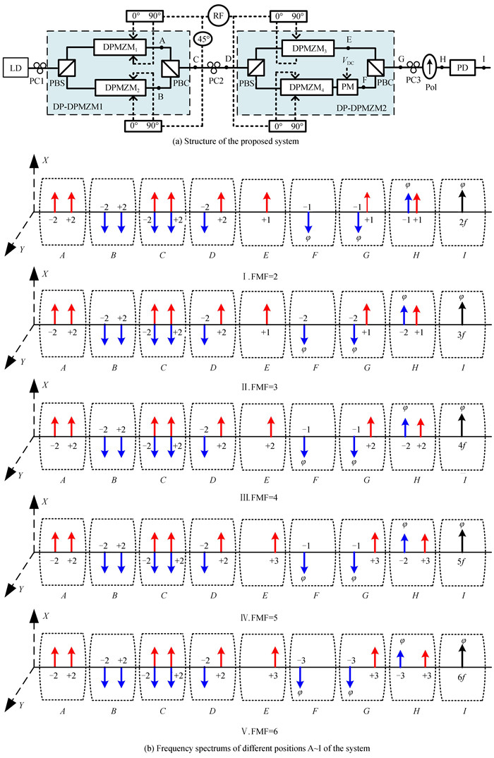
Fig. 1. Schematic diagram of the proposed photonic microwave phase-shifting system and the signal frequency spectrums at different positions
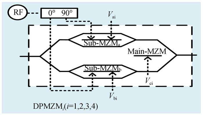
Fig. 2. Schematic diagram of DPMZMi (i= 1, 2, 3, 4)
Fig. 3. Optical spectrums of the DP-DPMZM1 output signal on two polarization directions
Fig. 4. Optical spectrums of the PC2 output signal on two polarization directions
Fig. 5. Optical spectrums of two sidebands with different frequency spacings of on the X -axis polarization direction after Pol
Fig. 6. Electrical spectrums of microwave signal with different FMFs after PD
Fig. 7. GHz output microwave signal with different phase shifts -180° to 180°
Fig. 8. Temporal waveforms of the microwave signal with different FMFs under different phase shifts
Fig. 9. OSSR and ESSR of the output microwave signal with different ER
Fig. 10. The output microwave signal phase drift Δφ and amplitude variation ΔA versus the DC driving voltageV DC at different phase shifts 80°≤θ ≤100° of 90°hybrid coupler
|
Table 1. The parmeter settings when the FMF of output microwave signal is 2, 3, 4, 5, 6

Set citation alerts for the article
Please enter your email address
© Copyright 2018-2021 | Chinese Laser Press. All Rights Reserved 沪ICP备15018463号-20