1Changchun Institute of Optics, Fine Mechanics and Physics, Chinese Academy of Sciences, Changchun 130033, China
2University of Chinese Academy of Sciences, Beijing 100049, China
3State Key Laboratory of Laser Interaction with Matter, Changchun Institute of Optics, Fine Mechanics and Physics, Chinese Academy of Sciences, Changchun 130033, China
Hongbo Shang, Luwei Zhang, Chunlai Liu, Ping Wang, Yongxin Sui, Huaijiang Yang. Optimization based on sensitivity for material birefringence in projection lens[J]. Chinese Optics Letters, 2020, 18(6): 062201
Copy Citation Text
Polarization aberration caused by material birefringence can be partially compensated by lens clocking. In this Letter, we propose a fast and efficient clocking optimization method. First, the material birefringence distribution is fitted by the orientation Zernike polynomials. On this basis, the birefringence sensitivity matrix of each lens element can be calculated. Then we derive the rotation matrix of the orientation Zernike polynomials and establish a mathematical model for clocking optimization. Finally, an optimization example is given to illustrate the efficiency of the new method. The result shows that the maximum RMS of retardation is reduced by 64% using only 48.99 s.
Polarization illumination is widely used in high numerical aperture (NA) projection lenses for better imaging resolution[1]. However, the desired polarization state of the illumination will be changed after light tracing through the projection lens due to polarization aberrations, and the imaging contrast is reduced accordingly. One of the factors that induce polarization aberrations is material birefringence. It causes a phase delay between the p-polarized light and the s-polarized light like a wave plate and changes the polarization state of the light entering the projection lens. In this Letter, we focus on the compensation of the material birefringence, which is of great importance for ensuring a high imaging quality for high NA projection lenses[2–4].
The material birefringence can be considered as a two-dimensional tolerance like surface figures and can be compensated by lens clocking[5]. Serebriakov et al. proposed a compensation method by setting a different azimuth angle for each element manually by using its regular intrinsic birefringence distribution[6]. This method cannot handle stress-induced birefringence, which is usually randomly distributed. The method does not consider the effects of actual ray paths and cannot get the best optimization results. In our previous work, we utilized the particle swarm optimization (PSO) method to solve the above problems, but it takes a long time to complete the optimization process. Moreover, the PSO method takes the optical system as a black box and cannot consider the details of the birefringence distribution of different lenses as well as their different influence on the system polarization aberration[7,8].
To achieve a fast and efficient compensation process, we propose a new clocking optimization method for birefringence based on a sensitivity matrix. Similar to fitting surface figures with a fringe Zernike, we use orientation Zernike polynomials (OZPs) to describe the birefringence distributions that can be measured by the material manufacturer or generated by the optical system designer[9–11]. Then we obtain the sensitivity matrix of birefringence for each element with the commercial software CODEV through real ray tracing. After that, the rotation matrix of the OZP is derived and the mathematical model for the new clocking method is established. Finally, an optimization example using the new method is illustrated and the result is compared with the PSO method.
Sign up for Chinese Optics Letters TOC. Get the latest issue of Chinese Optics Letters delivered right to you!Sign up now
Polarization aberrations can be represented by the Jones matrix, also known as the Jones pupil, which can be written as
According to the work of Geh et al., the Jones pupil of a projection lens can be decomposed by singular value decomposition (SVD) and can be written as[12]where represents the scalar transmission and represents the scalar phase; , , , , and represent the diattenuation value, bright axis direction, rotator angle, retardation value, and fast axis direction, respectively. In the projection lens, material birefringence is small and only induces retardations in the Jones pupil. The retardation matrix in Eq. (2) can be expressed as[13,14]where is the unit matrix. For the lithography lens, is quite small and can be approximated to . Then the retardation can be further decomposed as where indicates the radial part, which is the same as the radial part of fringe Zernike polynomials. The angular part is defined as
is defined as the orientation Zernike polynomials, which can be used to indicate the orientators. When the matrix elements in OZP correspond to the asymmetry terms in the fringe Zernike polynomials, the OZP labeling is
When the matrix elements in OZP correspond to the symmetry terms in the fringe Zernike polynomials, the OZP labeling is
Similar to the RMS value of the fringe Zernike polynomials, we can also calculate the RMS value of the OZP, as shown in the formula[8]where is Kronecker delta functions with the same in OZP.
Since the birefringence is an orientator, we can also fit it with OZP. In this Letter, ±36 items are used. On this basis, the sensitivity of the birefringence corresponding to each term is calculated and the optical system retardation caused by each lens element can be expressed as where is the sensitivity matrix of the th lens element; is the OZP coefficient of the th element birefringence, and is the OZP coefficient of the optical system retardation.
To complete the clocking compensation for material birefringence, we need to further establish the relationship between the system optimization function and the rotation angle of each lens element.
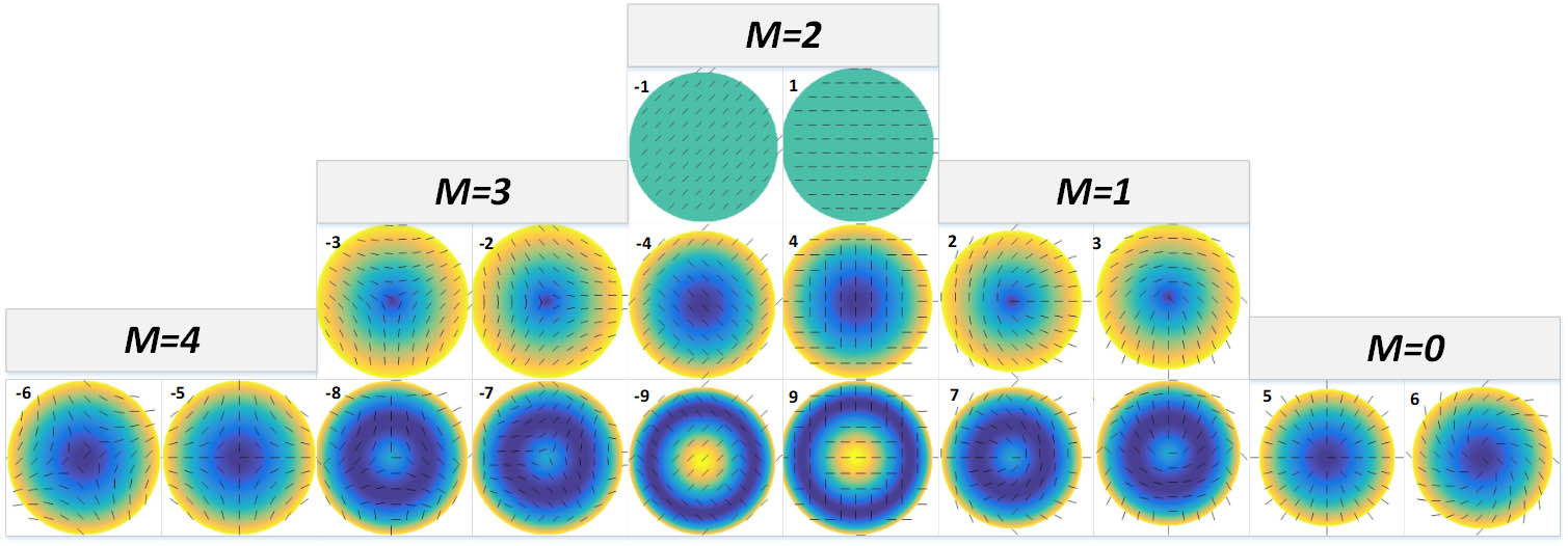
The distribution of the ±9 OZP terms is shown in Fig. 1. It can be found that OZP has -fold symmetry, which means that its distribution is unchanged after rotating around the center. The value is[14]
According to the symmetry of OZP, we can deduce the corresponding rotation formulas for and as
Then the rotation matrix for and can be written as
The rotation matrix for and is similar. For and , the corresponding rotation matrix is
After the lens element is rotated, its contribution to system retardation can be expressed as
For optical systems with lens elements and field points, the clocking optimization for birefringence can be simplified to the nonlinear least-squares (NLS) problems: where is the rotation angle for the th lens element.
We illustrate the effectiveness of the above method by taking a projection lens as an example. The parameters of the lens are shown in Table 2. The optical layout is shown in Fig. 2[15]. Three field points are set for optimization, which are 0 mm, 28 mm, and 56 mm, respectively.
The OZP coefficients of each lens element are randomly generated. The RMS values are between 0.2 nm/cm and 0.7 nm/cm. The birefringence map and corresponding OZP coefficients of three elements are shown in Figs. 3 and 4, respectively, to illustrate the random distributions, which are more complex than the intrinsic birefringence of [6].
Figure 3.Birefringence map. (a) Element 1, RMS value is 0.54 nm/cm and PV value is 1.16 nm/cm; (b) element 11, RMS value is 0.52 nm/cm and PV value is 1.26 nm/cm; (c) element 17, RMS value is 0.61 nm/cm and PV value is 1.49 nm/cm.
Using the commercial software CODEV, we can calculate the retardation pupil of the projection lens after loading birefringence data. The results are shown in Fig. 5, and the maximum retardation RMS is 7.80 nm. The OZP coefficients are shown in Fig. 6 and the maximum OZP term is with the coefficient of 7.13 nm.
Figure 5.Retardation pupil before optimization. (a) Field 1, RMS value is 7.80 nm; (b) field 2, RMS value is 7.07 nm; (c) field 3, RMS value is 6.29 nm.
Then the sensitivity matrix of each lens element for each field is calculated using MATLAB and CODEV. It takes 710.18 s using 20-core CPU parallel computing to implement the calculation, which is only needed to be conducted once for a certain lens. Finally the NLS optimization is conducted and the optimal rotation angles for each lens element are listed in Table 3.
Element number
Rotation angle (°)
Element number
Rotation angle (°)
1
−122.4877
12
−28.1719
2
151.9301
13
−130.8673
3
−18.5576
14
98.6486
4
−58.0564
15
163.6454
5
−166.2842
16
81.236
6
18.6296
17
53.6626
7
−40.8166
18
−41.0608
8
22.0181
19
139.3792
9
−26.4504
20
−102.1568
10
−8.5624
21
161.3852
11
163.3315
22
135.8173
Table 3. Rotation Angles for Each Lens Element After Optimization
After setting the optimization angles in CODEV, the system retardations are recalculated and the results are shown in Fig. 7. The maximum retardation RMS of the system is 2.77 nm and is reduced by 71.2%, 65.5%, and 56.0% separately for the three field points. It can also be found from Fig. 8 that most of the OZP terms are compensated and the maximum coefficient is below 2.2 nm.
Figure 7.Retardation pupil after optimization. (a) Field 1, RMS value is 2.25 nm; (b) field 2, RMS value is 2.45 nm; (c) field 3, RMS value is 2.77 nm.
At the same time, the NLS optimization method is compared with the PSO optimization method. As shown in Fig. 9, the optimization result of PSO is 2.61 nm, which is slightly better than the result of NLS. The reason is that the PSO randomly generates particles and does not use the gradient information of the system during optimization, which makes PSO more advantageous than NLS in finding the global optimal solution. However, the NLS method has two main advantages over PSO method: 1) NLS is more computing efficient, consuming only 48.99 s to implement optimization with 1-core CPU, while PSO needs 24421.84 s with 20-core CPU parallel computing; 2) when applying the NLS method, the birefringence sensitivity is calculated and we are able to get a deeper understanding of the contribution of each lens element for polarization aberration. Thus, in the actual manufacturing process of a projection lens, we can select the blank material in a targeted way to obtain faster and better compensation results.
Figure 9.Comparison of convergence between the PSO and NLS methods.
In conclusion, we have proposed a new optimization method called NLS that is based on the sensitivity matrix for birefringence compensation. An optimization example with an NA 0.93 projection lens has been presented to illustrate the performance of the NLS method. The maximum retardation RMS is reduced by 64% after optimization. The NLS method improves the optimization efficiency greatly and is helpful in blank material selection. Last, but not least, it could also be useful for birefringence, homogeneity, and surface figure clocking optimization in other high-precision optical systems.
Hongbo Shang, Luwei Zhang, Chunlai Liu, Ping Wang, Yongxin Sui, Huaijiang Yang. Optimization based on sensitivity for material birefringence in projection lens[J]. Chinese Optics Letters, 2020, 18(6): 062201