
Renyu Feng, Junyu Qian, Yujie Peng, Yanyan Li, Wenkai Li, Yuxin Leng, Ruxin Li, "Femtosecond infrared optical vortex lasers based on optical parametric amplification," High Power Laser Sci. Eng. 10, 05000e29 (2022)
- High Power Laser Science and Engineering
- Vol. 10, Issue 5, 05000e29 (2022)
Abstract
1
An optical vortex refers to a beam whose wavefront appears as a helical shape[1–3]. Due to the helical variation of the phase during propagation, there is an indeterminate phase singularity at the center of the beam and the field amplitude vanishes at the phase singularity, resulting in a ‘doughnut’ shape in the spatial intensity profile of the optical vortex beam. The phase of the optical vortex wavefront varies helically around a central point, from 0 to 2πl, where l is the topological charge number of the optical vortex. Unlike the spin angular momentum (SAM) of circularly polarized beam, the optical vortex beam of order ±l carries orbital angular momentum (OAM) of ±lħ per photon. Furthermore, the amount of OAM can be many times larger than that of the SAM by tuning the topological charge. The OAM and the intensity distribution of the doughnut make the optical vortices important for quantum information[4–6], optical manipulation[7,8], super-resolution microscopy[9–11] and materials processing[12]. However, in addition to the above traditional optical vortex applications, implanting OAM into an intense ultrashort light beam opens a broad range of new possibilities. Infrared femtosecond optical vortex lasers combine the advantages of traditional femtosecond lasers with vortex beams and have important applications in optical micro–nano manipulation[13], time-resolved nonlocal spectroscopy in solids[14] and proton acceleration[15]. Due to the transverse field structure of the optical vortex, transverse phase-matching is especially relevant in the generation of extreme ultraviolet vortex beams by high-order harmonics (HHGs)[16–18]. In particular, for the spectral region around 1.5 μm, femtosecond optical vortex lasers also have important applications in space division multiplexing[19,20] due to their proximity to the communication band. For terahertz experiments, optical vortex lasers at wavelengths of 1.5 μm can be used as the pump to generate terahertz vortex beams. For a pump wavelength between 1.4 and 1.6 μm, many THz generation crystals, such as DAST and DSTMS, are clearly very well phase matched with a generated frequency at 1 THz and above 1.5 THz[21,22]. Therefore, infrared femtosecond optical vortex lasers have an important role in extending the wavelength coverage of optical vortices and vortex-based strong-field physics.
Common optical vortices are generated by conventional mode converters, including spatial light modulators[23], spiral phase plates (SPPs)[24], cylindrical lens[25] and so on. However, all these converters suffer from common drawbacks, such as low power handling capabilities and limited wavelength coverage. Therefore, it is imperative to explore alternative techniques to generate high-power optical vortices over a wide wavelength range. Nonlinear frequency conversion has proven to be the most direct route to access various spectral domains across the electromagnetic spectrum. Recently, scientists have used nonlinear frequency conversion to achieve the output of different infrared optical vortices, including optical parametric generations (OPGs)[26], optical parametric oscillations (OPOs)[27–30] and optical parametric chirp pulse amplification (OPCPA)[31]. However, the generation of broadband ultrashort infrared optical vortices is still at the exploratory stage[32]. Also, based on nonlinear frequency conversion, optical parametric amplification (OPA) seeded with a white-light continuum (WLC) has the advantages of a high single-pass gain, broad tuning band, straightforward passive carrier-envelope-phase (CEP) control and being easier to operate[33,34]. Thus, OPA is an effective way to generate femtosecond infrared optical vortices.
In this paper, we report a two-color femtosecond infrared optical vortex laser system. Using a two-stage optical parametric amplifier, the 1.45 μm vortex signal beams converted by an SPP are amplified, and a 1.8 μm vortex idler laser is generated concomitantly. With this system, 1.45 μm vortex signal pulses with energy of 190 μJ and 1.8 μm vortex idler pulses with energy of 158 μJ have been obtained, and the pulse durations are 51 and 48 fs, respectively. This type of two-color femtosecond infrared optical vortex laser not only provides a stable, high-quality seed source for the building of OPCPA vortex laser systems, but also has a wide range of promising applications for vortex-based strong-field physics.
Sign up for High Power Laser Science and Engineering TOC. Get the latest issue of High Power Laser Science and Engineering delivered right to you!Sign up now
2 Experimental setup
The schematic of the infrared optical vortex laser system is presented in Figure 1. The system consists of a 1 kHz Ti:sapphire chirped pulse amplification (CPA) system (Astrella, Coherent, Inc.), a WLC generator, a 1.45 μm SPP for vortex conversion and a two-stage OPA system. The 1.5 mJ/800 nm pulses are used as the pump for OPA. In the laser system, the beam from the Ti:sapphire CPA is divided into three parts by two beam splitters (R/T = 90:10). A microjoule-level pulse energy passing through BS2 is focused on a 3 mm thick yttrium aluminum garnet (YAG) through the lens L, resulting in a broadband supercontinuum spectrum (over 2.1 μm) due to the self-phase modulation effect. One portion of the continuum light at approximately 1450 nm is used as the seed of the OPA. Owing to the high nonlinearity and broad phase-matching bandwidth, BaB2O4 (BBO) crystals (cut at θ = 27.4o for type-II phase-matching) are selected to amplify the signal. The BBO crystals used in the two OPA stages have sizes of 3 mm
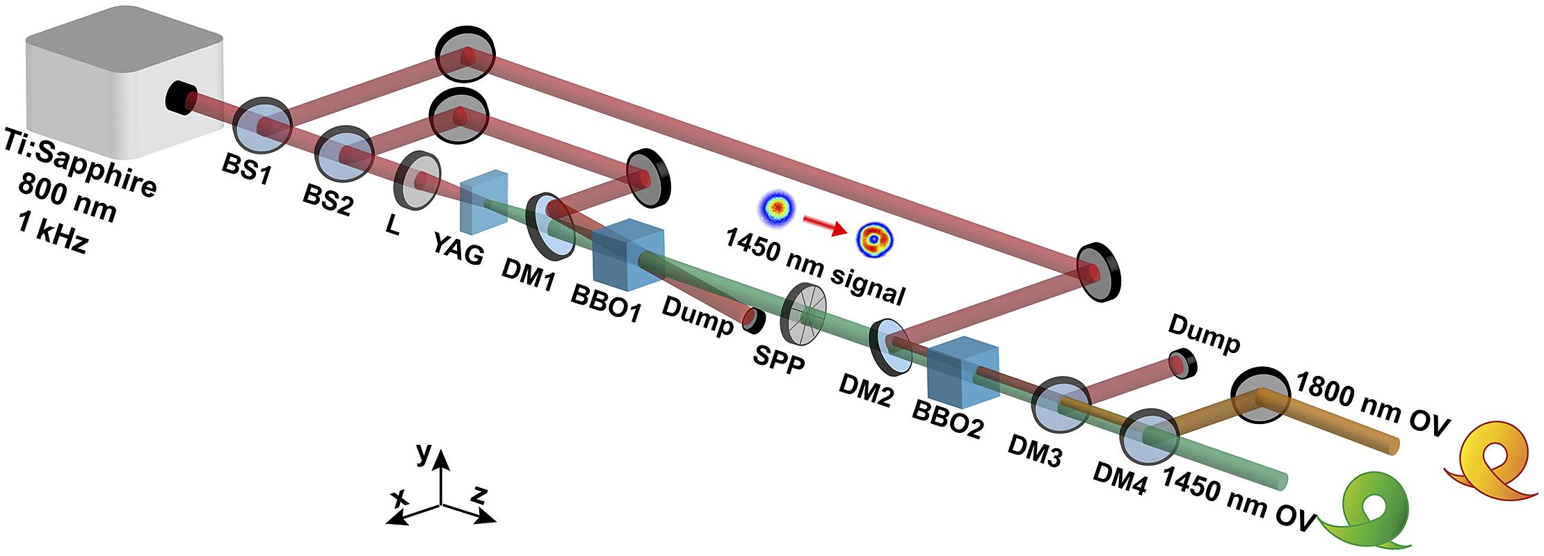
Figure 1.Schematic of the infrared vortex laser system. BS, beam splitter; L, lens; YAG, yttrium aluminum garnet crystal; DM, dichroic mirror; SPP, spiral phase plate; BBO, BaB2O4.
The SPP is made of a 3 mm quartz glass plate with the step height of 3250 nm. The refractive index of quartz at 1.45 μm is 1.445, and thus the 3250 nm step height corresponds to the 2π phase variation. The surface of the SPP is continuous and therefore the phase change of the resulting vortex light is also continuous.
Pump pulses of about 1.35 mJ reflected from BS1 are sent to the second collinear OPA stage. The vortex signal generated by the SPP is used as the seed of the second OPA stage. After amplification, the residual pump beam is reflected with DM3. DM4 is then used to separate the signal and idler beams. Finally, we achieve the output of the two-color optical vortex laser, 1.45 μm vortex signal pulses with energy of 190 μJ and 1.8 μm vortex idler pulses with energy of 158 μJ have been obtained and the pulse durations are 51 and 48 fs, respectively.
3 Results and discussion
Due to the wide gain bandwidth (full width at half maximum, FWHM) in the infrared wavelength band, high damage threshold and high nonlinear coefficient, BBO crystals are used in our two-stage OPA system. We simulate the phase-matching condition in the BBO crystal, and the results are shown in Figure 2(a). The type-II BBO crystal in the simulations has a length of 2 mm, and the pump and signal light are at approximately 800 nm and approximately 1450 nm, respectively. In Figure 2(a), the gain bandwidth of the idler light at 1800 nm is over 100 nm with θ = 27.4o. Therefore, we can use BBO crystals to obtain broadband femtosecond pulse output.
![]()
Figure 2.(a) Simulated phase-matching spectrum of the OPA process. (b) Spectra of the signal and the idler. (c) Calculated FTL pulse shapes of the signal and the idler.
In Figure 2(b), we show the signal and idler spectra obtained from the first-stage and second-stage OPAs, where the spectra of the signal and the idler have FWHMs of 70 and 100 nm, respectively. Then we calculated the Fourier-transform-limit (FTL) durations of the output spectra. The calculated shapes of the FTL pulses are shown in Figure 2(c), and the durations of the signal and the idler are 33 and 34.8 fs (FWHM), respectively. As shown in Figure 2(b), it can be seen that there are some deviations between the spectra of the first-stage OPA signal and those of the second-stage OPA signal. We adjust and optimize the phase-matching angle of the crystal according to the maximal conversion efficiency and output energy. When the conversion efficiency is highest or the output energy is maximum, the central wavelength of the output pulse will have some differences with the theoretically calculated central wavelength of phase-matching.
To verify the spatial and vortex features of the vortex beams, the spatial profiles of the signal and the idler amplified by OPAs have been measured by using a pyroelectric array charge-coupled device (CCD) camera (Spiricon Pyrocam IV) with the pixel size of 80 μm × 80 μm. As the results in Figures 3(a) and 3(c) show, the spot intensity distributions of the signal and the idler still maintain good doughnut shapes. However, the spot intensity distribution of the input pulses is uneven, which further aggravates the spot unevenness of the output pulses after being amplified by the second OPA stage. Since the wavefront change of the beam is not affected by parametric amplification, we speculate that the spot intensity inhomogeneities of the signal and the idler may be influenced by the unevenness of the crystal and lens surface and the step diffraction of the SPP.
![]()
Figure 3.(a) Spatial profile of the amplified 1.45 μm vortex output. (b) Self-interference fringes of the amplified 1.45 μm vortex. (c) Spatial profile of the amplified 1.8 μm vortex output. (d) Self-interference fringes of the amplified 1.8 μm vortex.
As shown in Figure 3, the topological charge of the vortex signal is +1, due to the conservation of the OAM of the parametric process:
The topological charge of the idler shall be –1 under the TEM00 pump. To investigate the wavefront characteristics of the vortex signal and the vortex idler, we have used a 50:50 beam splitter to split a portion of the pulses generated by the OPA. As shown in Figures 3(b) and 3(d), the two separated vortex beams perform dislocation interferences in the far field. The central bright bars have pairs of y-shaped stripes at the phase singularity (circled by white dashed circles), which also indicates that the pulse is a first-order optical vortex. Moreover, the vortex characteristics of the pulses are well preserved during the amplification process.
The temporal characterizations of the amplified signal and the generated idler pulses are measured by a home-built second-harmonic-generation frequency-resolved optical-gating (SHG-FROG) device[35]. The temporal and spectral pulse amplitude and phase of the vortex signal are shown in Figures 4(a) and 4(b). The measured pulse duration is 51 fs. The error of FROG reconstructed is about 0.3% over a 512
![]()
Figure 4.Temporal and spectral characterizations of the output pulses. (a) The pulse temporal profile of the duration (blue curve) and phase (orange curve) of the signal light at 1450 nm. (b) Reconstructed spectrum of the SHG-FROG (blue curve) and phase (orange curve) of the signal light at 1450 nm. (c) Measured and reconstructed SHG-FROG traces of the signal light at 1450 nm. (d) The pulse temporal profile of the duration (blue curve) and phase (orange curve) of the idler light at 1800 nm. (e) Reconstructed spectrum of the SHG-FROG (blue curve) and phase (orange curve) of the idler light at 1800 nm. (f) Measured and reconstructed SHG-FROG traces of the idler light at 1800 nm.
In the experiment, we use a stable laser source as the driving laser. During supercontinuum generation, a variable density filter and an iris diaphragm control the energy to produce a stable supercontinuum to give the OPA system a stable seed light. By using a stable seed light and optimizing the spatial and temporal coupling during amplification, we can improve the stability of the entire system as much as possible. To verify the stability of the vortex OPA device, we measured the energy and spectral stability of the output vortex signal pulses and the vortex idler pulses separately. In Figures 5(a)–5(c), the jitter of the output spectra is very weak. The root mean square (RMS) of the signal laser is less than 1.5% (within 1/e2 of spectral intensity), and the RMS of the idler laser is also less than 1.5%. In Figure 5(d), the energy fluctuation is 0.367% (RMS) for the signal pulses of 190 μJ, while the output idler energy is 158 μJ with the energy fluctuation of 0.457% (RMS). Thus, the stability of the output pulse energy and spectrum guarantees the long-term operation of the laser.
![]()
Figure 5.(a) Spectral stability of output pulses at 1450 and 1800 nm. (b) Spectral fluctuation of output pulses at 1800 nm. (c) Spectral fluctuation of output pulses at 1450 nm. (d) Energy stability of signal pulses (red dot) and idler pulses (blue dot).
4 Conclusions
In conclusion, we report a two-color femtosecond infrared optical vortex laser system based on OPA. Vortex signal pulses of 1.45 μm with energy of 190 μJ and 1.8 μm vortex idler pulses with energy of 158 μJ have been obtained, and the pulse durations are 51 and 48 fs, respectively. Moreover, we verified the topological charge of the amplified optical vortex by interference. The current optical vortex OPA device has a low output energy, as the input pulse energy is only 1.5 mJ. Subsequent work can further increase the pump pulse energy, and multi-mJ femtosecond infrared optical vortex can be obtained. This type of highly stable femtosecond infrared optical vortex laser source not only provides a stable, high-quality seed source for the building of OPCPA vortex laser systems, but also has a wide range of applications in time-resolved nonlocal spectroscopy in solids, optical communication and vortex-based strong-field physics.
References
[1] L. Allen, M. W. Beijersbergen, R. J. C. Spreeuw, J. P. Woerdman. Phys. Rev. A, 45, 8185(1992).
[2] A. M. Yao, M. J. Padgett. Adv. Opt. Photon., 3, 161(2011).
[3] M. Jan. Proc. SPIE, 5259, 66(2003).
[4] S. Gröblacher, T. Jennewein, A. Vaziri, G. Weihs, A. Zeilinger. New J. Phys., 8, 75(2006).
[5] R. Inoue, T. Yonehara, Y. Miyamoto, M. Koashi, M. Kozuma. Phys. Rev. Lett., 103, 110503(2009).
[6] A. Mair, A. Vaziri, G. Weihs, A. Zeilinger. Nature, 412, 313(2001).
[7] D. G. Grier. Nature, 424, 810(2003).
[8] J. E. Curtis, B. A. Koss, D. G. Grier. Opt. Commun., 207, 169(2002).
[9] S. Bretschneider, C. Eggeling, S. W. Hell. Phys. Rev. Lett., 98, 218103(2007).
[10] S. Berning, I. W. Katrin, H. Steffens, P. Dibaj, W. Hell Stefan. Science, 335, 551(2012).
[11] T. Watanabe, Y. Iketaki, T. Omatsu, K. Yamamoto, S.-i. Ishiuchi, M. Sakai, M. Fujii. Chem. Phys. Lett., 371, 634(2003).
[12] T. Omatsu, K. Chujo, K. Miyamoto, M. Okida, K. Nakamura, N. Aoki, R. Morita. Opt. Express, 18, 17967(2010).
[13] C. Hnatovsky, V. G. Shvedov, W. Krolikowski, A. V. Rode. Opt. Lett., 35, 3417(2010).
[14] B. G. Mendis. Ultramicroscopy, 157, 1(2015).
[15] X. Zhang, B. Shen, L. Zhang, J. Xu, X. Wang, W. Wang, L. Yi, Y. Shi. New J. Phys., 16, 123051(2014).
[16] C. Hernández-García, A. Picón, J. S. Román, L. Plaja. Phys. Rev. Lett., 111, 083602(2013).
[17] D. Gauthier, P. R. Ribič, G. Adhikary, A. Camper, C. Chappuis, R. Cucini, L. F. DiMauro, G. Dovillaire, F. Frassetto, R. Géneaux, P. Miotti, L. Poletto, B. Ressel, C. Spezzani, M. Stupar, T. Ruchon, G. De Ninno. Nat. Commun., 8, 14971(2017).
[18] L. Rego, M. D. Kevin, J. B. Nathan, L. N. Quynh, C.-T. Liao, J. S. Román, E. C. David, A. Liu, E. Pisanty, M. Lewenstein, L. Plaja, C. K. Henry, M. M. Margaret, C. Hernández-García. Science, 364(2019).
[19] N. Bozinovic, Y. Yue, Y. Ren, M. Tur, P. Kristensen, H. Huang, E. W. Alan, S. Ramachandran. Science, 340, 1545(2013).
[20] J. Wang, J.-Y. Yang, I. M. Fazal, N. Ahmed, Y. Yan, H. Huang, Y. Ren, Y. Yue, S. Dolinar, M. Tur, A. E. Willner. Nat. Photon., 6, 488(2012).
[21] L. Mutter, F. D. Brunner, Z. Yang, M. Jazbinšek, P. Günter. J. Opt. Soc. Am. B, 24, 2556(2007).
[22] M. Stillhart, A. Schneider, P. Günter, J. Opt. Soc. Am. B, 25, 1914(2008).
[23] N. R. Heckenberg, R. McDuff, C. P. Smith, A. G. White. Opt. Lett., 17, 221(1992).
[24] G. Ruffato, M. Massari, F. Romanato. Opt. Lett., 39, 5094(2014).
[25] M. W. Beijersbergen, L. Allen, H. E. L. O. van der Veen, J. P. Woerdman. Opt. Commun., 96, 123(1993).
[26] A. Aadhi, G. K. Samanta. J. Opt., 20, 01LT01(2017).
[27] H. Tong, G. Xie, Z. Qiao, Z. Qin, P. Yuan, J. Ma, L. Qian. Opt. Lett., 45, 989(2020).
[28] A. Aadhi, V. Sharma, R. P. Singh, G. K. Samanta. Opt. Lett., 42, 3674(2017).
[29] S. Araki, K. Ando, K. Miyamoto, T. Omatsu. Appl. Opt., 57, 620(2018).
[30] K. Miyamoto, S. Miyagi, M. Yamada, K. Furuki, N. Aoki, M. Okida, T. Omatsu. Opt. Express, 19, 12220(2011).
[31] J. Qian, Y. Peng, Y. Li, P. Wang, B. Shao, Z. Liu, Y. Leng, R. Li. Photon. Res., 8, 421(2020).
[32] H. Cao, R. S. Nagymihaly, M. Kalashnikov. Opt. Lett., 45, 3240(2020).
[33] B. Shao, Y. Li, Y. Peng, P. Wang, J. Qian, Y. Leng, R. Li. Opt. Lett., 45, 2215(2020).
[34] Y. Chen, Y. Li, W. Li, X. Guo, Y. Leng. Opt. Commun., 365, 7(2016).
[35] Y. Li, Y. Chen, W. Li, P. Wang, B. Shao, Y. Peng, Y. Leng. Opt. Laser Technol., 120, 105671(2019).


Set citation alerts for the article
Please enter your email address

© Copyright 2018-2021 | Chinese Laser Press. All Rights Reserved 沪ICP备15018463号-20