Gour Chandra Mandal, Rahul Mukherjee, Khaleda Mallick, Paulomi Mandal, and Ardhendu Sekhar Patra*
Abstract
We have projected and verified a bidirectional intra-/inter-radio-access-technology carrier-aggregation method for a next-generation heterogeneous mobile network supported by filter bank multicarrier (FBMC). Successful transmission of intra/inter-band carrier aggregation between five broadband FBMC signals and three bands 4G long-term-evolution-advanced signal over 50 km single-mode fiber plus 10 m free-space is successfully broadcasted by employing an incoherent light-injection scheme in downlink. In uplink, two intra-bands carrier-aggregated wireless local area network Institute of Electrical and Electronics Engineers 802.11g signal is carried over the equal distance. High receiver sensitivity, low error vector magnitude, and clear constellation diagrams show successful delivery of different wireless services for different consumers. Therefore, the proposed hybrid system should become a potential solution for a future mobile front-haul network because of its low latency and high capacity.Driven by the continuous demands of various bandwidth-hungry applications and legacy services due to mobile devices, the current mobile cellular networks have fueled into the continual upgradation, which promotes the cellular industry, and researchers to look for new radio-access technologies (RATs) to provide higher capacity with increased flexibility to a variety of users for the next-generation access network, namely, the fifth-generation (5G) system[1–3]. The major technical requirements of next-generation are higher RF band exploration, discrete-spectral-band utilization, small-cell deployment, Internet of Things (IoT), and gigabit wireless connectivity. To fulfil the ever-increasing bandwidth demand, a radio-over-fiber (RoF) wavelength division multiplexed (WDM) passive optical network (PON) is a key solution due to the advantages of both enormous capacity of fiber and flexibility via wireless delivery with favorable cost[4]. So, a next-generation network should be a hybrid optical/wireless integrated and carrier-aggregated (CA) heterogeneous network (Het-Net) using different frequency bands for different data rate requirements and coverage, namely, multi-RAT network architecture to realize spectrally efficient optical transmission to support high data rates and to increase the area of coverage. A simple, cost-effective, multi-wavelength light source and modulation method at the transmitting site should be required for practical deployment of the RoF-WDM-PON into one single network with high effectiveness. The external injection-locking[5,6] method on a Fabry–Perot laser diode (FPLD) plays a big role as an affordable and user friendly optical source because of several benefits, like increasing the side mode suppression ratio (SMSR), low value of relative intensity noise (RIN) and frequency chirp. The orthogonal frequency division multiplexing (OFDM) technique has been widely used in many 4G long-term-evolution-advanced (LTE-A) systems due to its various advantages, like better spectral efficiency (SE) and robustness against dispersion[7–13]. However, OFDM is not taken for granted for the next-generation RoF network because of several drawbacks, such as high spectral leakage, cross-band interference in multi-band scenarios, and strict synchronization requirements, that recently motivated research and industrial communities to propose new waveforms to keep the advantages of OFDM while addressing its shortcomings[14–16]. The filter bank multicarrier (FBMC) method does not need to include a cyclic prefix for each symbol due to the use of both FBMC prototype filters and the offset quadrature amplitude modulation (OQAM) scheme, and these lead to increases in the system capacity and enable the asynchronous CA. So, FBMC is a promising option for next-generation that not only lowers out-of-band emissions but also reduces the requirement for synchronization[15,16]. Lots of RATs based on new multicarrier waveforms were proposed and studied previously as a potential candidate to increase the SE in the next-generation communication network[14–16].
In this Letter, we propose and experimentally demonstrate a bidirectional intra-/inter-RAT CA scheme for providing simultaneous 4G and next-generation services in heterogeneous RoF-WDM-PON based on FBMC and the incoherent light-injection scheme.
An amplified spontaneous emission (ASE) injection-locked FPLD is used to produce two optical carriers. Five broadband asynchronous FBMC signals with a total bandwidth of 4.2 GHz at 60 GHz millimeter-wave (MMW) are inter-RAT aggregated with three bands of an LTE-A signal of a total bandwidth of 60 MHz and simultaneously transmitted over a 50 km single-mode fiber (SMF), as well as 10 m RF wireless link in downlink (DL). In uplink (UL), we successfully broadcast an intra-band CA wireless local area network (WLAN) Institute of Electrical and Electronics Engineers (IEEE) 802.11g signal of 40 MHz over the same distance. The verified results of the integrated LTE-A signal with an FBMC signal also confirm that the FBMC-based new RAT is compatible with the current Het-Net LTE system. The proposed fiber-wireless integrated and CA RoF Het-Net must be suitable for a high-speed and low-latency mobile front-haul transmission system.
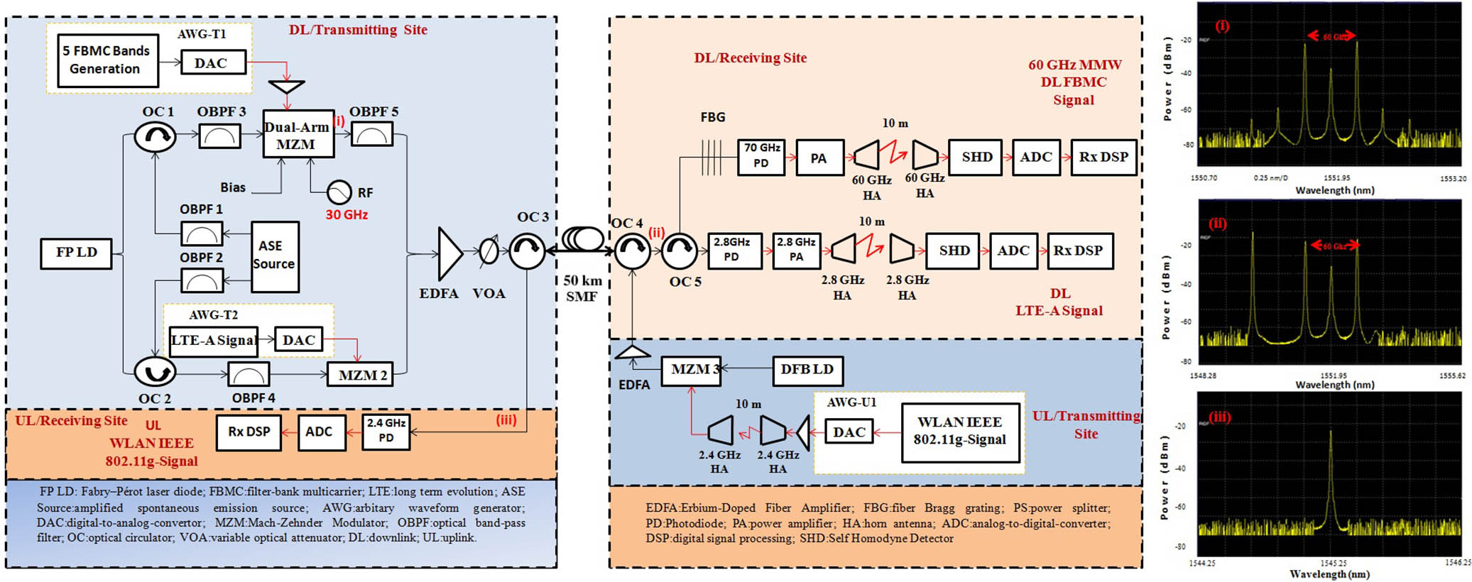
Figure 1 shows the experimental setup of the proposed full-duplex intra-/inter-RAT CA scheme for providing simultaneous 4G and next-generation services in heterogeneous RoF-WDM-PON based on FBMC. The two wavelengths of 1549.75 nm () and 1551.95 nm () have been carefully selected from a broadband ASE source employing two optical band-pass filters (OBPF1 and OBPF2), with 3 dB bandwidth of 0.3 nm, for matching with the two longitudinal modes of FPLD. Light is injected into the FPLD from the ASE through port 1 of optical circulators (OC1 and OC2). The light-injected FPLD is split into two parts by a optical splitter and fed into ports 2 of OC1 and OC2, and ports 3 of these OCs are coupled into OBPF3 and OBPF4 with 3 dB bandwidth of 0.6 nm for filtering out one light-injected mode. One branch of is used for MMW-RoF signal generation of FBMC signal modulation, and the other of is modulated with real time LTE-A signals. The designed parameters of the multi-sub-band FBMC signal and intra-band CA LTE-A signal are given in Table 1. The frequency response of the Mirabbasi–Martin filter can be written as[16,17]where is a very well known parameter to control the out-of-band response of filter frequency, and is the overlapping factor. From Ref. [16], it is observed that the reduction of out-of-band leakage is enough when the value is set to four. A dual-arm Mach–Zehnder modulator (MZM) is modulated with five FBMC sub-band signals generated from an arbitrary waveform generator (AWG) and 30 GHz RF signal at a carrier wavelength of to generate 60 GHz MMW and then filtered out by OBPF5 with 3 dB bandwidth of 0.48 nm to remove unwanted optical sidebands. The dual-arm MZM is operated at the quadrature point with half wave voltage of 6.0 V and biased at the minimum transmission point to suppress the central optical carrier. The other branch of is modulated by MZM2 with an intra-band CA LTE-A signal at 2.8 GHz, which consists of three 20 MHz-carrier components (CCs) of a total bandwidth 60 MHz. Both modulated optical signals of and are coupled via a optical coupler and then optically amplified by an erbium-doped fiber amplifier (EDFA). A variable optical attenuator (VOA) is enclosed after the EDFA to regulate the optical power level, and afterward the signal is transmitted into a bidirectional 50 km SMF via OC3. The EDFA has the length of 5 m and the gain of 20 dB, the VOA has the attenuation value of 10 dB, and the fiber has transmission loss of 0.25 dB/km and also the dispersion of 16.75 ps/(nm·km). At the base station (BS), the optical signal is fed into port 1 of the three-port OC5 via OC4. A fiber Bragg grating (FBG, ) with a 3 dB bandwidth of 0.3 nm, loss of 0.1 dB, and a reflection ratio of 90% is coupled with port 2 of OC5 to reflect the LTE-A signal, whereas the FBMC signal passes to a 70 GHz positive-intrinsic-negative (PIN) photo detector (PD) to detect MMW FBMC signal. The detected electrical signal is boosted by a 60 GHz power amplifier (PA) with output power of 15 dBm and wirelessly transmitted by a horn antenna (HA) with gain of 25 dBi. After broadcasting over a 10 m free-space link, the signal is received by another HA and down-converted to the original signals by a self-homodyne detector (SHD)[18]. Finally, the broadband signals are sampled and stored by a digital scope for offline signal processing. Port 3 of OC5 passes through a 2.8 GHz PD as a DL LTE-A detector and 2.8 GHz PA, a pair of 2.8 GHz HAs for 10 m wireless transmission, and an SHD for down-conversion to the original signals before they are sampled by a digital scope and demodulated offline. While the UL-aggregated signal is externally modulated on a carrier from a distributed-feedback (DFB) LD with an intra-band CA WLAN IEEE 802.11g signal at 2.4 GHz, two 20 MHz CCs of total bandwidth 40 MHz are comprised, as given in Table 1. The UL signal passes through the EDFA to boost the signal and fed into same 50 km SMF through OC4. Then, the WLAN is detected by a 2.4 GHz PD and sampled by a digital scope.
| Parameters | Values |
|---|
| • For 5 sub-bands FBMC signal |
| Modulation format | 16 QAM | 64 QAM |
| Number of bits | 102,400 | 153,600 |
| Bit rate | 8 Gb/s | 12 Gb/s |
| Sampling frequency | 40 GS/s |
| Sub-bands spacing | 781.25 kHz |
| One sub-band bandwidth | 800 MHz |
| Multi-sub-bands bandwidth | 4.24 GHz |
| Filtering | Mirabbasi–Martin (k=4) |
| IFFT/FFT size | 1024 |
| Time window | 12.8 μs |
| RRC roll off | 0.3 |
| • For intra-bands DL LTE-A signal |
| Modulation format | 16 QAM | 64 QAM |
| Each carrier bandwidth | 20 MHz |
| Signal BW | 60 MHz |
| • For intra-bands UL WLAN IEEE 802.11g signal |
| Modulation format | 16 QAM | 64 QAM |
| Each carrier bandwidth | 20 MHz |
| Signal BW | 40 MHz |
Table 1. System Parameters

Figure 1.Experimental configuration of the proposed bidirectional carrier aggregation in next-generation radio-over-fiber heterogeneous networks based on FBMC. Insets (i)–(iii) are the optical spectra.
The best case was observed when the injection wavelength is close to the one of the lasing mode of the slave FPLD with a lower front-facet reflectance of 1%, which gives the slave colorless FPLD a wider gain spectrum with flexible mode selectivity and provides a higher injection-locking efficiency. The incoherent light injection promotes the mode competition of selected longitudinal modes of the slave FPLD laser biased at 50 mA () at 28°C, which decreases the RIN induced by non-coherent spontaneous emission, such that the modulation bandwidth (from 7.9 to 10.8 GHz) of the slave laser can be enlarged. Figure 2 shows the RIN level of the slave LD, which will be reduced with incoherent injection locking. Injection locking at shifts up the RIN peak frequency of the slave LD from 7.9 to 10.8 GHz and suppresses it from to . So, the noise figures are often diminished by exploitation of the incoherent light-injection technique, which can decrease the RIN value from the laser cavity for improving the signal to noise ratio (SNR) of the carried data. The optical spectrum of the free-running FPLD is shown in Fig. 3(a). It can be found that FPLD inherently possesses a wide spectrum (1548–1556 nm), but the multiple modes of the FPLD are often tuned into two-mode characteristics when two wavelengths (1549.75 and 1551.95 nm) from the master source (ASE) are suitably injected. The stable injection-locked range of the FPLD is specified by[4]where denotes coupling coefficient between the laser field and injection field, and are the laser and injection field intensity, and represents the linewidth enhancement factor. is the locking range, where is the frequency of the master laser, and is the frequency of the free-running slave laser. The frequency of the master ASE source is slightly higher than that of the slave FPLD source for the optimum incoherent light-injection condition. Two modes from the FPLD with wavelengths of 1549.60 and 1551.82 nm have been carefully selected, and incoherent light injection is found at the negative detuning of 0.15 and 0.13 nm for the injected wavelengths of 1549.75 and 1551.95 nm, respectively. The SMSR values are evaluated of and for two incoherent light-injected modes, presented in Fig. 3(b). The optical spectra of the DL LTE-A and 60 GHz MMW FBMC signals are shown in Figs. 3(c) and 3(d), respectively.
Figure 2.RIN of FPLD.
Figure 3.Optical spectra of (a) free running FPLD, (b) two incoherent light injected modes of FPLD, (c) DL three intra-bands CA LTE-A signal, and (d) DL five intra-bands CA MMW FBMC signal.
Figure 4(a) represents the measured average error vector magnitude (EVM) values of 16-QAM and 64-QAM of the composite five sub-bands FBMC signal as a function of the received optical power. The constellation diagrams at the received optical power of for both 16-QAM and 64-QAM cases are also shown as insets in Figs. 4(a)–4(c). We can observe clear constellation diagrams with clearly separated clusters for both 16 and 64-QAM signals, confirming a good transmission quality of the system. This experiment achieved EVM below 12.5% for 16-QAM and 8% for 64-QAM as a figure of merit, as proposed by the Third Generation Partnership Project (3GPP) LTE[19]. These limits were achieved for received optical power of and for 16-QAM and 64-QAM, respectively. Power penalties of 2.4 and 3 dB are observed for 16 and 64-QAM between back-to-back and 50 km SMF, plus 10 m wireless scenarios from the results of Fig. 4(a). Moreover, Fig. 4(b) indicates the calculated average EVM values of 16 and 64-QAM of the three intra-band CA LTE-A signals as a function of the received optical power. Figure 4(b) shows that the received optical powers of and for 16 and 64-QAM are required to achieve the 3GPP LTE-A EVM percentage limit, and the results of Fig. 4(b) also show that there are about 2.5 and 3 dB power penalties for 16 and 64-QAM after traversing the distance. From the constellation diagrams and following results, it is clear that both OFDM and FBMC show comparable performances in DL. In comparison, FBMC performs much better with a large bandwidth under quasi-gapless carrier aggregation due to its smaller inter-band crosstalk. For UL transmission, the measured average EVM values of two intra-band CA UL WLAN IEEE 802.11g signals as a function of received optical power of 16 and 64-QAM are shown in Fig. 4(c).
Figure 4.Average EVMs of (a) five intra-bands CA DL FBMC signal as a function of received optical power, (b) three intra-bands CA DL LTE-A signal as a function of received optical power, and (c) two intra-bands CA UL WLAN IEEE 802.11g signal as a function of received optical power.
The optical powers of and for 16 and 64-QAM are received for UL transmission. Power penalties of 3.5 and 4 dB are observed for 16 and 64-QAM, respectively, between the two transmission scenarios. This power penalty may be assigned to fiber dispersion after 50 km SMF transport and RF power degradation over 10 m wireless transport. Figures 5(a)–5(c) show the received electrical spectra of different signals for DL and UL.
Figure 5.Electrical spectra of received (a) DL five intra-bands CA FBMC, (b) DL three intra-bands CA LTE-A, and (c) UL two intra-bands CA WLAN IEEE 802.11g signals.
A novel full-duplex inter-/intra-RAT CA scheme for providing simultaneous 4G and next-generation services in Het-Nets based on FBMC is proposed and experimentally demonstrated to deliver DL five intra-bands CA FBMC signals and three intra-bands CA LTE-A signals, as well as UL two intra-bands CA WLAN IEEE 802.11g signals simultaneously. With the assistance of the incoherent light-injection technique at the DL/transmitting site, high-performance SHD at the receiving site, very good spectrum, and clear constellation diagrams, low EVM values and small power penalties are achieved in our planned setup. The bit error rates (BERs) of 16-QAM are , , , and of 64-QAM are , , , with SNRs of 17.7, 17.8, 17.5 dB for 16-QAM and 17.2, 17.3, 17.0 dB for 64-QAM for FBMC, LTE-A, and WLAN signals, respectively. So, we believe that the aggregated FBMC-based new RAT will meet the expectations for next-generation wireless communications with high capacity and low latency for multi-user and multi-band high-speed mobile networks.
References
[1] L. Cheng, M. Zhu, M. M. U. Gul, X. Ma, G.-K. Chang. J. Lightw. Technol., 32, 1907(2014).
[2] A. Osseiran, F. Boccardi, V. Braun, K. Kusume, P. Marsch, M. Maternia, O. Queseth, M. Schellmann, H. Schotten, H. Taoka, H. Tullberg, M. A. Uusitalo, B. Timus, M. Fallgren. IEEE Commun. Mag., 52, 26(2014).
[3] G. C. Mandal, R. Mukherjee, B. Das, A. S. Patra. Opt. Commun., 411, 138(2018).
[4] G. C. Mandal, R. Mukherjee, B. Das, A. S. Patra. Int. J. Electron. Commun. (AEÜ), 80, 193(2017).
[5] H.-Y. Chen, Y.-C. Chi, G.-R. Lin. Opt. Express, 23, 22691(2015).
[6] G. C. Mandal, R. Mukherjee, B. Das, A. S. Patra. Opt. Commun., 427, 202(2018).
[7] C.-T. Tsai, C.-H. Lin, C.-T. Lin, Y.-C. Chi, G.-R. Lin. Sci. Rep., 6, 27919(2016).
[8] C.-Y. Lin, Y.-C. Chi, C.-T. Tsai, H.-Y. Wang, G.-R. Lin. IEEE J. Sel. Topics Quantum Electron., 21, 1801810(2015).
[9] C.-Y. Chen, P.-Y. Wu, H.-H. Lu, Y.-P. Lin, J.-Y. Wen, F.-C. Hu. Opt. Lett., 38, 2345(2013).
[10] C.-H. Chang, P.-C. Peng, H.-W. Gu, C.-W. Huang, F. Meng-Hsin, H.-L. Hu, P.-T. Shen, C. Y. Li, H.-H. Lu. IEEE Photon. J., 7, 7903708(2015).
[11] K. Mallick, R. Mukherjee, B. Das, G. C. Mandal, A. S. Patra. Int. J. Electron. Commun. (AEÜ), 96, 260(2018).
[12] Z.-K. Weng, Y.-C. Chi, H.-Y. Kao, C.-T. Tsai, H.-Y. Wang, G.-R. Lin. J. Lightw. Technol., 36, 4282(2018).
[13] C.-T. Tsai, Y.-C. Chi, G.-R. Lin. IEEE J. Sel. Topics Quantum Electron., 23, 1700309(2017).
[14] H. N. Parajuli, H. Shams, L. G. Gonzalez, E. Udvary, C. Renaud, J. Mitchell. Opt. Express, 26, 7306(2018).
[15] M. Xu, J. Zhang, F. Lu, J. Wang, L. Cheng, H. J. Cho, M. I. Khalil, D. Guidotti, G.-K. Chang. IEEE Photon. Technol. Lett., 28, 1912(2016).
[16] J. Zhang, M. Xu, J. Wang, F. Lu, L. Cheng, H. Cho, K. Ying, J. Yu, G.-K. Chang. J. Lightwave Technol., 35, 989(2017).
[17] A. Sahin, I. Guvenc, H. Arslan. IEEE Commun. Surv. Tutorials, 16, 1312(2014).
[18] B. J. Puttnam, R. S. Luis, J. M. Delgado Mendinueta, J. Sakaguchi, W. Klaus, Y. Kamio, M. Nakamura, N. Wada, Y. Awaji, A. Kanno, T. Kawanishi, T. Miyazaki. Photonics, 1, 110(2014).
[19] LTE; Evolved universal terrestrial radio access (E-UTRA); Base station (BS) radio transmission and reception(2015).