
Hanh N. D. Le, Ryan Decker, Axel Krieger, Jin U. Kang. Experimental assessment of a 3-D plenoptic endoscopic imaging system[J]. Chinese Optics Letters, 2017, 15(5): 051701
- Chinese Optics Letters
- Vol. 15, Issue 5, 051701 (2017)
Abstract
Endoscopic imaging provides visualization in minimally invasive surgery and helps reduce the trauma associated with open procedures[
Stereoscopy uses a passive wide-field illumination and acquires two images of an object from two viewing angles to reconstruct depth information via disparity searching. The depth resolution ranges from 0.05 to 0.6 mm[
ToF techniques measure the differences in phase and intensity of time or frequency modulated laser pulses. Depth information can hence be reconstructed with low computational cost based on the active light modulation information. However, depth resolution based on ToF is relatively poor from 0.89 to 4 mm[
Sign up for Chinese Optics Letters TOC. Get the latest issue of Chinese Optics Letters delivered right to you!Sign up now
The structured illumination technique is classical in 3-D reconstruction, with its principle based either on disparity searching, similar to the stereoscopy technique[
In addition to the three techniques described above, plenoptic imaging is a fairly new 3-D reconstruction technique in the biomedical field. The technique involves a microlens array (MLA) integrated onto an imaging sensor, such that each point of the object can be viewed and imaged at different angles via adjacent microlenses. The depth information can be deduced similarly to the stereoscopy approach. However, in stereoscopy, the two imagers should maintain a set angle of separation to obtain two distinct views of the object while ensuring the desired depth accuracy[
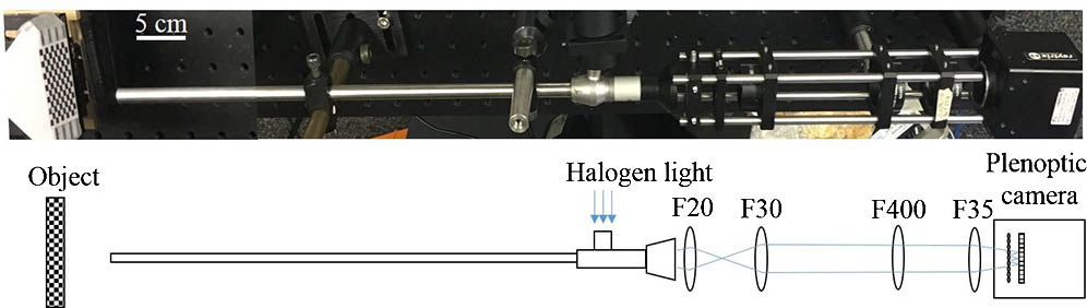
The endoscopic setup described in Fig.
![]()
Figure 1.Schematic of the endoscopic setup with the plenoptic camera and relay lens system.
In the plenoptic imaging setting, a main lens produces an image from a real object; this image then acts as the object for the MLA. Through the MLA, the incident light cone is split into multiple subimages collected by the sensor. Based on these collected microlens images, depth calculation is defined by the relation between the calculated virtual depth and the metric transformation relation[
Depth calculation of a plenoptic setup relates to stereoscopy technology, where the MLA performs as a micro camera array that generates multiple views of a small portion of the object, which is also the image generated by the main lens. First, a correspondence search is established with each pixel location from one micro sensor correlated with the other pixel location from the adjacent micro sensor using the sum of the absolute difference method over a group of pixel points along the epipolar lines. The method searches for corresponding pixels between the two adjacent micro images by minimizing the absolute difference between the pixel values within a window size,
Once the correlated pixels of these micro images are determined, the intersection point of projected rays through these pixels into the virtual 3-D space determines the virtual depth of the object. This virtual depth is related to the distance between the observed object and the camera. An example depicted in Fig.
![]()
Figure 2.Triangulation principle for virtual depth estimation. IP: Image plane.
From the virtual depth information, metric distance
As the optical property of the endoscope is proprietary, the overall system magnification is unknown theoretically; however, we determine the system magnification empirically using a known measurement height standard. Therefore, the scaled object height is determined using this magnification.
To evaluate the system performance, we calculate the depth of field (DOF) via the resolution and contrast measurement within a range of working distances. The resolution is the smallest resolvable width of a horizontal or vertical line on a USAF test target 1951 (R3L3S1 P, Thorlabs, New Jersey, USA). The standard target is moved away from the distal end of the borescope without refocusing, with an equal step size of 5 mm and increasing the located distance from 10 to 50 mm. In addition, a contrast change with the set working distance was also recorded. The resolution and DOF plot in Fig.
![]()
Figure 3.Resolution and contrast measurements.
To further validate the system’s accuracy and precision, we used a checkerboard pattern with a known square size of 3.5 mm on a DOF target serving as the height standard (DOF 5-15, Edmund Optics, Barrington, New Jersey). The target is aligned at 0° and 45° and 20 mm away from the distal end plane of the borescope, as indicated in Figs.
![]()
Figure 4.(a) Microlens image of the checker board at 0° with (b) its depth map and (c, d) point cloud data at different views.
![]()
Figure 5.Microlens image of the checker board at 45° with (b) its depth map and (c, d) point cloud data at different views.
Due to the triangulation, the depth reconstruction is only possible when sufficient object features and local contrast are achieved, such as at the edges and corners of the checkerboard, as observed in Figs.
| 0° | 45° | ||
|---|---|---|---|
| Accuracy | Mean | 0.085 | 0.818 |
| Standard deviation | 0.032 | 0.440 | |
| Maximum | 0.103 | 1.439 | |
| Precision | Mean | 1.141 | 2.367 |
| Standard deviation | 0.721 | 1.800 | |
| Maximum | 3.863 | 11.658 |
Table 1. Reconstruction Accuracy and Precision at Two Planar Angle Deviations at 0° and 45° (Unit: mm)
A finer grid pattern for testing the system’s accuracy and precision in Figs.
Other complicated 3-D-printed objects of polydimethylsiloxane material with defined structures and known dimensions were further used to examine the system spatial reconstruction. The result indicates the distinct curvature and heights of the objects with the displayed depth colormap (see Fig.
![]()
Figure 6.(a–c) Microlens image of a plane and inhomogeneous objects and (d–f) its reconstructed depth maps.
![]()
Figure 7.(a) Microlens image of a fowl ventricular specimen and (b–d) its 3-D reconstructions at multiple angles.
Due to the nature of the plenoptic technique for searching for the disparity between adjacent microlens images, the reconstruction algorithm depends strongly on the inherent features of the tested samples. In other words, featureless or homogeneous regions of the object create outliers or missing depth information, thus data interpolation is essential. To compensate for this limitation, a projector can be used to actively illuminate known features onto the object and an efficient illumination setting can be used to resolve the finer details of the object as well as to avoid reflectance saturation. Nonexistent data points have no effect on the accuracy and precision. The depth estimation depends on detectable features that could be maximized by using active illumination. There are a few advantages of plenoptic endoscopy with active illumination over normal structured illumination. The first is that the plenoptic approach allows the user to observe the scene from a variety of angles in both horizontal and vertical directions due to the MLA arrangement. The second is that the entire scene can be brought into focus provided that it is within the FOV. Lastly, the structure of the illumination needs not be known beforehand, and is not a source of error. Typical structured light approaches rely on a precisely known projection pattern, whereas the plenoptic approach seeks only high contrast features, which can be provided in a myriad of ways.
In conclusion, a 3-D endoscopic system using a plenoptic imaging technique is demonstrated with reconstructed dimensions of both planar and complex samples. We are currently working with the research and development team at the Raytrix Company to further improve the design of MLA that will benefit from such endoscopic 3-D vision for minimally invasive surgery. The improvement involves the f-matching performance of aperture size between the MLA and the optics of the commercial surgical borescope, while maintaining an adequate frame rate for surgical guidance purpose (10 frames per second). Moreover, other optical analysis techniques, such as multispectral imaging or laser speckle contrast, can be registered onto the 3-D rendering to provide the dynamic properties of the studied tissue in minimally invasive surgery.
References
[1] P. Bucher, F. Pugin, S. Ostermann, F. Ris, M. Chilcott, P. Morel. Surg. Endosc., 25, 408(2011).
[2] C. M. Kang, D. H. Kim, W. J. Lee, H. S. Chi. Surg. Endosc., 25, 2004(2011).
[3] R. Smith, A. Day, T. Rockall, K. Ballard, M. Bailey, I. Jourdan. Surg. Endosc., 26, 1522(2012).
[6] N. Atzpadin, P. Kauff, O. Schreer. IEEE Trans. Circuits Syst. Video Technol., 14, 321(2004).
[7] D. Stoyanov, M. V. Scarzanella, P. Pratt, G. Z. Yang. Med. Image Comput. Comput. Assist. Intervention, 6361, 275(2010).
[8] D. Stoyanov. Med. Image Comput. Comput. Assist. Interv., 7510, 479(2012).
[9] P. L. Chang, D. Stoyanov, A. Davison, P. E. Edwards. Med. Image Comput. Comput. Assist. Interv., 8149, 42(2013).
[10] J. Penne, K. Höller, M. Stürmer, T. Schrauder, A. Schneider, R. Engelbrecht, H. Feußner, B. Schmauss, J. Hornegger. Med. Image Comput. Comput. Assist. Interv., 5761, 467(2009).
[14] S. Zhang. Opt. Lasers Eng., 48, 149(2010).
[15] H. Du, Z. Wang. Opt. Lett., 32, 2438(2007).
[16] T. T. Wu, J. Y. Qu. Opt. Express, 15, 10421(2007).
[17] C. Schmalz, F. Forster, A. Schick, E. Angelopoulou. Med. Image Anal., 16, 1063(2012).
[18] J. Yagnik, G. S. Gorthi, K. R. Ramakrishnan, L. K. Rao. TENCON 2005–2005 IEEE Region 10 Conference, 1(2005).
[19] T. Hain, R. Eckhardt, K. Kunzi-Rapp, B. Schmitz. Med. Laser Appl., 17, 55(2002).
[22] . 3D Imaging with NI LabVIEW(2016).
[23] R. Rao. Stereo and 3D vision(2009).
[24] H. Nguyen, Z. Wang, J. Quisberth. Adv. Opt. Methods Exp. Mech., 3, 195(2016).
[25] T. Georgiev, A. Lumsdaine. Proc. SPIE, 8299, 829908(2012).
[26] C. Perwass, L. Wietzke. Proc. SPIE, 8291, 829108(2012).
[27] R. Decker, A. Shademan, J. Opfermann, S. Leonard, P. C. Kim, A. Krieger. Proc. SPIE, 9494, 94940B(2015).
[28] A. Shademan, R. S. Decker, J. Opfermann, S. Leonard, P. C. Kim, A. Krieger. IEEE International Conference on Robotics and Automation (ICRA), 708(2016).
[29] C. Heinze, S. Spyropoulos, S. Hussmann, C. Perwass. IEEE Trans. Instrum. Meas., 65, 1197(2016).
[30] O. Johannsen, C. Heinze, B. Goldluecke, C. Perwaß. On the calibration of focused plenoptic cameras. Time-of-Flight and Depth Imaging. Sensors, Algorithms, and Applications, 302(2013).

Set citation alerts for the article
Please enter your email address
© Copyright 2018-2021 | Chinese Laser Press. All Rights Reserved 沪ICP备15018463号-20