Maki Maeda, Jameesh Keloth, Síle Nic Chormaic, "Manipulation of polarization topology using a Fabry–Pérot fiber cavity with a higher-order mode optical nanofiber," Photonics Res. 11, 1029 (2023)
Copy Citation Text
Optical nanofiber cavity research has mainly focused on the fundamental mode. Here, a Fabry–Pérot fiber cavity with an optical nanofiber supporting the higher-order modes (, , , and ) is demonstrated. Using cavity spectroscopy, with mode imaging and analysis, we observed cavity resonances that exhibited complex, inhomogeneous states of polarization with topological features containing Stokes singularities such as C-points, Poincaré vortices, and L-lines. In situ tuning of the intracavity birefringence enabled the desired profile and polarization of the cavity mode to be obtained. We believe these findings open new research possibilities for cold atom manipulation and multimode cavity quantum electrodynamics using the evanescent fields of higher-order mode optical nanofibers.
1. INTRODUCTION
Novel phenomena that can be revealed in nonparaxial light, such as transverse spin and spin-orbit coupling, have led to increasing interest in the tightly confined light observed in nano-optical devices [1]. Optical nanofibers (ONFs), where the waist is subwavelength in size, are useful in this context because they provide very tight radial confinement of the electric field and facilitate diffraction-free propagation over several centimeters [2]. Most ONF research focuses on single-mode ONFs (SM-ONFs) that only support the fundamental mode . In contrast, higher-order mode ONFs (HOM-ONFs), fabricated from few-mode optical fiber, can guide HOMs, such as , , , and [3]. In the weakly guided regime, which is generally used to describe light propagation in standard optical fiber, this group of modes can be viewed to form the linearly polarized mode . To date, there has been a lot of attention paid to HOM-ONFs in theoretical work [4–10] than in experimental work due to the difficulty in precisely controlling the fiber waist size and obtaining selective mode excitation at the waist [3,11,12].
In principle, there are many interesting phenomena that can be explored with an HOM-ONF. For example, it has been proposed that the relationship between spin angular momentum (SAM) and orbital angular momentum (OAM) can be studied [5,10,13,14]. Additionally, it was proposed that an HOM-ONF could be used to trap and manipulate cold atoms [4,15,16]. Fabrication of an ONF that supports the HOMs was achieved [3,17,18] and subsequently HOM-ONFs were shown to manipulate dielectric microbeads more efficiently in the evanescent field than SM-ONFs [19,20]. Other experimental work has shown that when cold atoms also interact with HOMs, detected signals are stronger than when one uses an SM-ONF only [21].
Introducing a cavity system to the ONF could further increase light–matter interactions due to cavity quantum electrodynamics (cQED) effects [22–24]. To date, numerous types of SM-ONF-based cavities have been proposed [25–30] and the interactions of their resonance modes with various quantum emitters have been studied [31–33]. Strong light–atom coupling using SM-ONF-based Fabry–Pérot and ring resonators has already been achieved [34,35]. Superstrong coupling of cold atoms and multiple longitudinal modes of a long fiber-ring resonator consisting of an SM-ONF section was demonstrated [36]. Using multiple degenerate higher-order transverse modes in free-space has been shown to exhibit strong coupling [37,38], further illustrating the importance of realizing an HOM-ONF-based cavity system at this point. The advantages are not only for enhanced interactions via cQED effects, but also for a better overall understanding of the behavior of the modes in such a cavity.
Sign up for Photonics Research TOC. Get the latest issue of Photonics Research delivered right to you!Sign up now
Studying the behavior of the HOM-ONF cavity spectrum and the cavity mode profiles gives additional insight into the nature of the HOMs themselves, as well as how they interfere with each other and interact with the external environment. The generation of and modes in a laser cavity consisting of a microfiber directional coupler-based mode converter was previously demonstrated [39]. However, earlier attempts to realize a passive HOM optical microfiber cavity did not yield any resonant peaks in the cavity spectrum apart from the fundamental modes; in other words, the typical donut- or lobe-shaped intensity profiles associated with HOMs were not observed [40], primarily due to challenges when engineering the taper profile to minimize losses at the taper transitions.
The inhomogeneous polarization structure of HOMs must be considered when studying a fiber cavity system with an HOM-ONF. In recent years, complex polarization distributions and the generation of polarization singularities have been investigated using various methods, giving rise to the relatively new field of singular optics [41]. Polarization singularities are a subset of Stokes singularities; i.e., phase singularity points in Stokes phases [42,43]. In fact, higher-order fiber eigenmodes are vector optical fields with a polarization singularity called a V-point, where the state of polarization (SOP) (i.e., how the polarization is distributed in the cross-section of a given mode), is undefined [41]. Other types of Stokes singularities can be formed in elliptical optical fields, such as the polarization singularity of C-points, where the polarization orientation is undefined [41,42], and Poincaré vortices, where the polarization handedness is undefined [43–45]. Moreover, points of linear polarization can form continuous lines, which are classified as L-lines [41].
The generation of all Stokes singularities within a single beam has been demonstrated using a free-space interferometer [43,46]. Modal interference in a birefringent crystal can facilitate the creation of polarization singularities [47,48]. As a result, the SOP can significantly vary along the propagation length, with C-points and L-lines propagating as C-lines (i.e., continuous lines of circular polarization) and L-surfaces (i.e., surfaces of linear polarization) [47–49]. Moreover, polarization singularities can appear, move or disappear from a given cross-sectional region with a smooth and continuous change of birefringence [50]. Birefringent media were used to create laser cavity modes containing a polarization singularity [51,52]. These experiments were limited to the generation of low-order V-points due to a lack of control of the amplitude, phase, and SOP, all of which would be required to create other types of polarization singularities [41]. A few-mode optical fiber cavity has the potential to generate complex laser modes by its highly variable degree of birefringence.
Interference and birefringence are generally inseparable properties in fibers. The modal interference pattern in a fiber changes continually with a periodicity of when the relative phase between modes is changed between 0 to as the eigenmodes propagate along the fiber [53]. This effect was used in a few-mode optical fiber to generate ellipse fields containing a C-point [54,55]. Due to the increasing complexities of modal interference in few-mode fibers, filtering for the desired set of HOMs, and selectively exciting them to generate and manipulate polarization singularities, are necessary. Realizing a fiber cavity containing an ONF should enable both spatial and frequency filtering for selective excitation of HOMs, as well as enhancement of the resonant mode coupling effect [56,57].
In this paper, we experimentally demonstrate an HOM-ONF-based Fabry–Pérot fiber cavity. The transverse polarization topology of any given resonant mode is determined by selecting modes from the cavity spectra and analyzing the images of the transmitted mode profile. We also demonstrate in situ intracavity manipulation of the modal birefringence to change the amplitude, frequency position, and the SOP of the modes. We believe this work is a significant step toward gaining full control of the evanescent field at the HOM-ONF waist and extends the range of applications for which such nanodevices could be used.
2. METHODS
A. Experiments
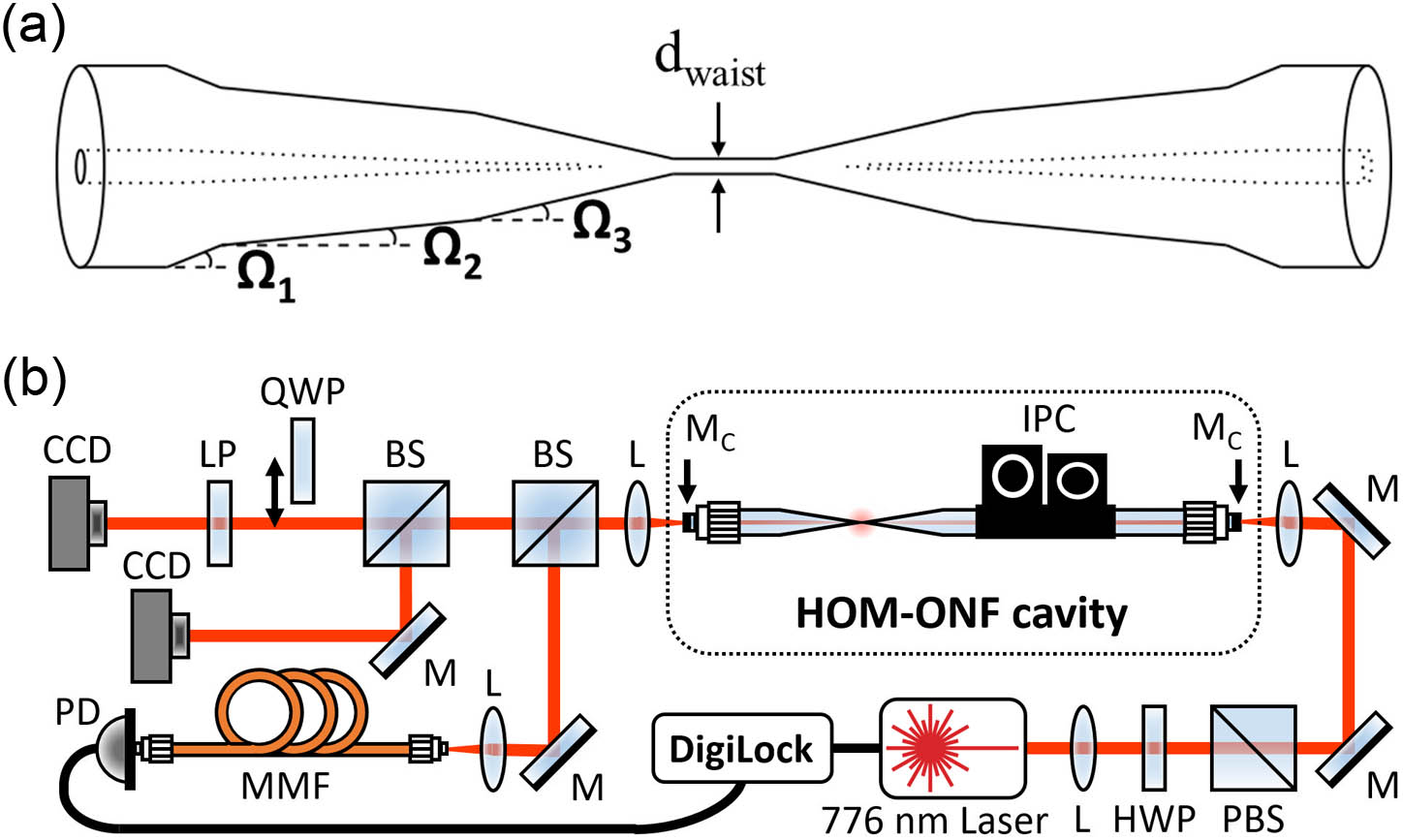
For the HOMs described in Section 1 to propagate throughout the cavity with an HOM-ONF, the nanofiber must be with low loss for the entire set of modes. Tapered fibers were drawn from SM1250 (9/80) fiber (Fibercore) using an oxy-hydrogen flame pulling rig. The untapered fiber supports the , , , and modes at a wavelength . The modes supported by tapered fiber depend on tapering profile and waist diameter. We used two different tapered fibers with waist diameters of (i) for SM behavior ( and ) and (ii) for the HOM-ONF, which supports , , , , , and . The shape of the tapered fibers was chosen to be trilinear, as shown in Fig. 1(a), with angles of , , and to be adiabatic for the and modes. Fiber transmission following the tapering process was for the fundamental mode.
Figure 1.(a) Sketch of tapered optical fiber with trilinear shape. , waist diameter. (b) Schematic of experimental setup. L, lens; HWP, half-wave plate; PBS, polarizing beam splitter; M, mirror; , cavity mirror; IPC, in-line polarization controller; BS, beam splitter; QWP, quarter-wave plate, which was inserted to calculate ; LP, linear polarizer; CCD, camera; MMF, multimode fiber; and PD, photodiode.
A sketch of the experimental setup is given in Fig. 1(b). The cavity was fabricated by splicing each pigtail of the tapered fiber to a commercial fiber Bragg grating (FBG) mirror (Omega Optical). The two FBG mirrors consisted of stacked dielectric mirrors coated on the end faces of fiber patch cords [SM1250 (9/80), Fibercore] and had a reflectivity of 97% at . Both mirrors had almost the same reflectivity over all input polarization angles ( variation). The cavity also contained an in-line polarization controller (IPC), as shown in Fig. 1(b), to manipulate the birefringence inside the cavity. Moving the paddles of the IPC induced stress and strain in the fiber, thereby changing the effective cavity length. A typical cavity length was , which was physically measured and estimated from the cavity free-spectral range (FSR).
A linearly polarized Gaussian beam from a laser at (Toptica DL100 pro) was launched into the fiber cavity. The laser frequency was either scanned or locked to a mode of interest using a Pound–Drever–Hall locking module (Digilock110, Toptica Photonics). The cavity output beam was split into three paths: one for the laser feedback controller to observe the cavity spectra and to lock to specific modes, one to image the spatial profile of the modes with a CCD camera, and one to analyze the transverse SOP of each mode using a removable quarter-wave plate (QWP), a rotating linear polarizer, and a CCD camera, as shown in Fig. 1(b). Six intensity profile images were taken in total for each mode. Four images were taken without the QWP and with the linear polarizer angle set to 0° (), 45° (), 90° (), and 135° (), and two images were taken by inserting the QWP set to 90° while the polarizer was set to 45° () and 135° (). The SOPs were determined by analyzing the six profile images using Stokes polarimetry. Furthermore, the Stokes phase and Stokes index were determined [41] (see Section 2.C).
B. Simulations
Each mode experiences arbitrary birefringence as it propagates along the fiber. The total field in the fiber at any point is the sum of the propagating modes with a corresponding phase shift. The addition of FBG mirrors to the fiber induces an additional birefringence [56,57], which can be incorporated in a single birefringence matrix. Note that this model does not include cavity boundary conditions since we only aimed to simulate the spatial profiles of the fiber modes. We calculated an arbitrary fiber field due to interference and birefringence by taking a summation over different fiber modes, so where is the number of eigenmodes to be interfered, is the electric field of a fiber eigenmode , , , and , with being the azimuthal mode order that defines the helical phase front and the associated phase gradient in the fiber transverse plane. is the radial mode order, which indicates the th solution of the corresponding eigenvalue equation [5]. is the amplitude, is the phase between modes, and represents the arbitrary birefringence Jones matrix of each eigenmode , so that where is the relative phase retardation induced between the fast axis and the slow axis, and is the orientation of the fast axis with respect to the horizontal axis; i.e., perpendicular to mode propagation.
Let us now consider the system with an ONF supporting , , , , , and , so that the number of modes that can be interfered is . The cross-sectional profiles and SOPs of and are shown in Figs. 2(a) and 2(b), respectively. The and modes are not shown here but their vector fields are orthogonal to the and at every point. These modes have donut-shaped mode profiles with linearly polarized vector fields at any point in the mode cross-section. As an example of possible fiber modes using Eq. (1), Fig. 2(c) illustrates in-phase interference of the and modes with equal amplitudes. The resulting mode has a lobe-shaped intensity pattern with scalar fields. Figure 2(d) is an example of a mode resulting from the interference of the circularly polarized and the out-of-phase (a phase difference) and with equal amplitudes. The SOP, which overlaps on the intensity profile images marked as red and blue ellipses, corresponds to right- and left-handed orientations, respectively. This mode is the so-called lemon [55], which contains not only linear polarization, but also elliptical and circular polarization components in one mode.
Figure 2.Simulations of (a) , (b) , (c) , and (d) lemon. The red and blue SOPs indicate right- and left-handed ellipticities, respectively. The scale bars show the normalized intensity (from 0 to 1) and the Stokes phase (from 0 to ). Stokes singularity points of , , and are indicated as pink, orange, and blue dots, respectively. An L-line is indicated in green.
When using Eq. (1) to simulate mode profiles, several eigenmodes with similar intensity patterns and SOPs to an experimentally observed cavity mode were selected as the initial conditions. Next, the variables , , , and were tuned to match the experimentally observed cavity mode intensities, SOPs, and Stokes phases. Polarization topological defects in the simulated modes were then identified, using the method described in Section 2.C.
C. Analysis
The polarization gradient was calculated to identify Stokes singularities in the cross-section of the mode. The gradient map is known as the Stokes phase , which is given by [42,45] where and are Stokes parameters with in order, and . The phase uncertainty points (i.e., Stokes singularities), were identified by obtaining the Stokes indices , which are defined as [42,45] where is the counterclockwise azimuthal change of the Stokes phase around the Stokes singularity. Singularities of are known as V-points and C-points, in vector and ellipse fields, respectively [42]. Singularities of and are known as Poincaré vortices [43–45]. L-lines are located where . Table 1 is a summary of the classification of the Stokes singularity types in terms of the Stokes phases and singularity indices with the corresponding polarizations in the vector and ellipse fields [43,45,46,58].
List of Stokes Singularities in Vector Fields (v) and Ellipse Fields (e) by the Singularity Index, , Using the Stokes Phase, , with in Order
Stokes singularity
Stokes phase
Stokes index/Phase values
Polarization
V-point (v)
Null
C-point (e)
R/L
Poincaré vortex (e)
H/V
D/A
L-line (e)
0, ,
Linear
The Stokes singularity points and L-lines were found from the Stokes phases, then superimposed and marked on the mode profiles. As examples, from Figs. 2(a) and 2(b), the center of the mode profiles for both and contains a V-point, with and (pink dot), respectively. These points were found from their Stokes phases [lower panels in Figs. 2(a) and 2(b)]. In contrast, the lemon mode in Fig. 2(d) has a closed loop representing an L-line (green) and all three types of Stokes singularities: a C-point with (pink dot), Poincaré vortices with and (orange dots), and and (blue dots) were found from , , and , respectively. The lobe-shaped scalar mode in Fig. 2(c) does not have a gradient in any associated Stoke phases, since topological defects can only exist in nonscalar fields [41].
3. RESULTS AND DISCUSSION
A. Cavity with a Single-Mode Optical Nanofiber
As an initial experimental test, the spectrum for an HOM cavity containing an ONF of waist diameter was obtained, as shown in Fig. 3(a). This ONF waist can only support the fundamental modes. The IPC paddle angles were set so that two distinct, well-separated modes with minimal spectral overlap were observed. The finesses of Modes 1 and 2 in Fig. 3(a) were 12 and 15, respectively. The laser was locked to each of these two cavity modes consecutively and the mode profiles were observed at the output end face of the fiber cavity. The corresponding mode intensity profiles, SOPs, and Stokes phases are shown in Figs. 3(b)(i) and 3(b)(ii). The intensity profiles for both Modes 1 and 2 were slightly skewed Gaussian shapes. The eigenmode intensity shape is Gaussian, so the slight deviation from the expected shape may be attributed to aberrations in the optical beam path. In terms of polarization distribution, the Stokes phases of Modes 1 and 2 were uniform; in other words, their SOPs were scalar fields, regardless of the IPC paddle angles chosen, as expected for the mode.
Figure 3.(a) Typical spectrum for an HOM cavity with an SM-ONF as the laser is scanned over 150 MHz. The spectrum over a single FSR is indicated by the red box. (b) Mode intensity profiles showing the SOPs (top) and corresponding Stokes phases (bottom) for (i) Mode 1 and (ii) Mode 2. The red and blue SOPs indicate right- and left-handed ellipticities, respectively. The scale bars show the normalized intensity (from 0 to 1) and the Stokes phase (from 0 to ).
Although the pretapered fiber supported the full set of eigenmodes in , , and , when the ONF with a diameter was inserted between the two sets of mirrors, only one or two modes with quasi-Gaussian profiles were observed, no matter which IPC paddle angles were chosen. The HOMs were filtered out due to the tapered fiber waist being SM, analogous to an intracavity pinhole spatial filter. Mode filtering as a function of the ONF waist diameter was experimentally observed [17]. Here, however, we could additionally observe the mode filtering effect on the cavity spectrum and SOP of each mode.
In an ideal SM-ONF cavity with no birefringence, there are two degenerate orthogonal modes. However, due to random birefringence of the fiber and the cavity mirrors, the two modes become nondegenerate; i.e., separated in frequency, leading to coupling between the modes [59]. Mode coupling of orthogonal modes can occur in a birefringent medium and this effect can increase in a cavity configuration [60]. Mode coupling in an ONF cavity due to asymmetrical mirrors has been previously discussed [56] and experimental evidence of mode coupling due to intrinsic birefringence in an SM-ONF cavity has already been reported [57]. In our experiments, nonorthogonal combinations of SOPs were observed, as seen in Figs. 3(b)(i) and 3(b)(ii). Mode 1 was horizontally polarized [red/blue lines in Fig. 3(b)(i)], while Mode 2 was left elliptically polarized [blue ellipse in Fig. 3(b)(ii)]. By adjusting the IPC paddle angles, it was possible to change the phase relationship and coupling between the and modes, and shift between orthogonal and nonorthogonal combinations of SOPs.
B. Cavity with a Higher-Order Mode Optical Nanofiber
Next, the spectrum for an HOM cavity containing an ONF of waist diameter was obtained, as shown in Fig. 4(a). This ONF can support the , , , , and modes. The IPC paddle angles were set to obtain the maximum number of well-resolved modes in a single FSR, as shown in Fig. 4(a). One can clearly see five distinct peaks indicating that the HOM-ONF does not degrade the modes in the cavity and the finesses of the cavity modes are high enough to resolve them. The finesses of Modes 1 to 5 were 12, 16, 13, 22, and 13, respectively. The mode finesse values of the cavity with an HOM-ONF were in the same range as those for the cavity with an SM-ONF [Fig. 3(a)], implying that the HOM-ONF was adiabatic for the group of modes. The laser was locked to each of the cavity modes consecutively and the mode profiles were observed at the output of the fiber cavity. The corresponding mode intensity profiles, SOPs, and Stokes phases are shown in Figs. 4(b)(i)–4(b)(iv). In the spectrum shown in Fig. 4(a), there were five distinctive modes, but locking to Mode 3 was not possible because of its close proximity to the dominant Mode 4.
Figure 4.(a) Typical spectrum for a cavity with an HOM-ONF as the laser is scanned over 150 MHz. The spectrum over a single FSR is indicated by the red box. (b) Mode intensity profiles showing the SOP (top) and the corresponding Stokes phases (bottom) for (i) Mode 1, (ii) Mode 2, (iii) Mode 4, and (iv) Mode 5. The red and blue SOPs indicate right-handed and left-handed ellipticities, respectively. The scale bars show the normalized intensity (from 0 to 1) and the Stokes phase (from 0 to ). Stokes singularity points of , , and are indicated as pink, orange, and blue dots, respectively. L-lines are indicated in green. (c) Corresponding simulated results.
Two flat-top intensity profiles were observed in Modes 1 and 4, as shown in Figs. 4(b)(i) and 4(b)(iii). The SOPs of these modes are markedly different from those for the Gaussian-type modes in Figs. 3(b)(i) and 3(b)(ii), which have simple scalar SOPs. Modes 1 and 4 were inhomogeneously polarized ellipse fields, showing regions of left and right circular polarizations divided by an L-line [Figs. 4(b)(i)–4(b)(iii)]. The center of these two modes exhibited diagonal and anti-diagonal polarizations, respectively; i.e., the SOPs at the center of the modes were orthogonal to each other. Going toward the edges of the modes, the polarization changes from linear to circular, with opposite handedness on either side of the L-lines. Notice also in Fig. 4(a) that Modes 1 and 4 are not well frequency separated from the neighboring modes. This suggests that the mode profiles and SOPs of these modes were not only affected by birefringence and degenerate modal interference, but also some nondegenerate modal interference with neighboring cavity modes [60]. Additionally, for Mode 4, we identified two C-points (), indicated by the pink dots in Fig. 4(b)(iii), where the value of changed by , as shown in Table 1. The interference of with modes from the group can generate C-points in few-mode fiber [55], as shown in Fig. 2(d).
We performed basic simulations to determine if combinations of and some mode(s) in the family could generate similar mode profiles and SOP structures to those in Figs. 4(b)(i) and 4(b)(iii). The simulated results are shown in Figs. 4(c)(i) and 4(c)(iii). The and modes were selected as possible contributors and their amplitudes, phase, and birefringence fitting parameters were tuned to match the experimental results. Modes 1 and 4, as shown in Figs. 4(c)(i) and 4(c)(iii), could have been formed from different mode combinations rather than our assumed and ; however, these modes were very likely formed by interference between and some mode(s) of the group, resulting in their inhomogeneous SOPs and flat-top shapes.
We also observed two distorted lobe-shaped modes (Modes 2 and 5), as shown in Figs. 4(b)(ii) and 4(b)(iv). The lobe-shaped pattern also arises from modal interference between modes in the family [see Fig. 2(c) for an example]. With reference to Table 1, Mode 2 in Fig. 4(b)(ii), showed all three types of Stokes singularities, indicated by pink dots for C-points () and orange/blue dots for Poincaré vortices (), as presented in , , and , respectively. A single mode containing all Stokes singularities has been demonstrated using free-space interferometers [43,46]; here, we generated them within a single mode using a fiber cavity system. Mode 5 in Fig. 4(b)(iv), also had two C-points () and a Poincaré vortex () as seen in and , respectively. Figure 4(a) shows that Modes 2 and 5 are not well frequency separated from Modes 1 and 4, respectively. Therefore, there is likely a contribution from the mode, resulting in a distortion of the lobe shape.
To simulate Mode 2 in Fig. 4(b)(ii), we combined , , and , and to simulate Mode 5 in Fig. 4(b)(iv), we used , , and . The amplitude of each mode, phase shift, and birefringence parameters were adjusted to achieve a close fit. The simulated results are shown in Figs. 4(c)(ii) and 4(c)(iv). These plots are not exact replications of the experimental results since the parameter space is large and the exact initial conditions are not known; nevertheless, the matches are reasonably close.
Interestingly, many of the cavity modes obtained in different sets of spectra, which were generated using different IPC paddle angles, exhibited Stokes singularities. Polarization singularities are known to propagate through a birefringent medium as C-lines and L-surfaces and their evolution is affected by the homogeneity of the birefringence along the propagation path [47–49]. This phenomenon is due to the conservation of the topological charge [49,58,61], and the Stokes index value remains constant [58]. However, our cavity is an inhomogeneous birefringent medium because it contains a number of different birefringent elements such as the FBG mirrors and the IPC; as such, the degree of birefringence varies along the propagation direction. Therefore, the presence of Stokes singularities in the imaged field at the cavity output does not necessarily guarantee the existence of such topological defects in the ONF region. Nonetheless, singularity points can enter, move, and exit with a smooth and continuous variation of birefringence [50]. Therefore, the SOP is expected to evolve along the length of the cavity, with singularity points shifting and making numerous entries and exits in the cross-section profile of the modes. However, since the ONF waist is relatively straight and uniform, the birefringence variation at the waist should be minimal [62] and topological features appearing at the start of the waist should be preserved every along the waist. It is also important to note that the strong confinement at the waist induces a large longitudinal electric field component that should perturb the local polarization and intensity patterns [5]. As a result, the spatial mode profiles that were observed in the experiments may not be identical to the spatial mode profiles at the waist. Indeed, this has already been experimentally demonstrated for tightly focused free-space C-points as Möbius [63,64] and ribbon strips [65], as well as pure transverse spin [64]. To date, none of these unique nonparaxial phenomena have been observed in the evanescent fields of ONFs. We believe that our cavity has great potential to experimentally uncover such phenomena in this regime.
Theoretically, as mentioned earlier, the HOM-ONF can support a total of six eigenmodes. Therefore, one might expect that the spectrum should show six distinct modes. However, we typically observed three to five distinct peaks in a single FSR depending on the IPC paddle angles. This could be explained by the lack of sufficient finesse to resolve all modes, some of which are closely overlapped [60]. However, it may be feasible to increase the mode finesses by increasing the mirror reflectivity and using an ONF with lower transmission loss than the one used; the estimated loss of Mode 4, the highest finesse in Fig. 4(a), was . Nonetheless, the finesse values of our long cavity with an HOM-ONF should be sufficient for cQED experiments with narrow linewidth emitters such as cold atoms.
C. In situ Higher-Order Cavity Mode Tuning
A key feature of this setup is the ability to tune the spectrum and SOP to create the desired mode in the cavity. We aimed to observe modes with donut-shaped intensity patterns and SOPs similar to the fiber eigenmodes [Fig. 2(a)], , , and [Fig. 2(b)]. To achieve this, the laser was locked to a well-resolved lobe-shaped mode. The paddle angles of the IPC were then adjusted, and the mode shape was monitored with a CCD camera until a donut mode profile was observed. Unlocking and scanning the laser revealed a new spectrum, with each mode containing a new profile. The IPC was adjusted again to maximize another mode and the laser was locked to this new mode. The IPC paddle angles were tuned to convert the mode profile once more to a donut shape. This procedure was repeated for four different modes, as shown in Figs. 5(a)(i)–5(a)(iv), and these modes look similar to the true fiber eigenmodes of, respectively, [Fig. 2(b)], , [Fig. 2(a)], and . There was a slight deformation from a perfect donut shape and their SOPs were not vector fields, but rather ellipse fields with alternating regions of opposite handedness. While the donut eigenmodes possessed a V-point at the center as indicated by the pink dots in Figs. 2(a) and 2(b), the observed quasi-donut modes in Figs. 5(a)(i)-5(a)(iv) had some nominal intensity at the center. These modes had two C-points of or near the center [see the pink dots in Figs. 5(a)(i)–5(a)(iv)], as opposed to a single point of or in the true eigenmodes [Figs. 2(a) and 2(b)]. Indeed, perturbation of vector field polarization singularities can occur when scalar linearly polarized beams are interfered [66].
Figure 5.(a) Mode intensity profiles for quasi-donut-shaped cavity modes from the cavity containing an HOM-ONF with their SOPs (top) and Stokes phases (bottom) similar to the fiber eigenmodes of (i) , (ii) , (iii) , and (iv) . The red and blue SOPs indicate right-handed and left-handed ellipticities, respectively. Scale bars show intensity (from 0 to 1) and Stokes phase (from 0 to ). Stokes singularities of , , and are indicated as pink, orange, and blue dots, respectively. L-lines are illustrated as green lines. (b) Corresponding simulated results.
These donut-shaped cavity modes were also simulated, as shown in Figs. 5(b)(i)–5(b)(iv). To obtain a good fit for the experimentally observed intensities, SOPs, and Stokes phases in Figs. 5(a)(i)–5(a)(iv), the simulated modes included a slight deformation of the donut shape by adding some components of the mode to modes in the group. Moreover, the simulated results show that the Stokes phases are very similar to those obtained experimentally. The number of possible combinations of modal interference with varying birefringence is large and this leads to discrepancies between the experiment and simulation. However, these findings indicate that the experimentally observed quasi-donut modes are likely the result of residual interference between the mode and modes in the group. Degeneracy of multiple modes may be avoided by increasing the cavity mode finesses so that each mode can be well separated. The system demonstrated here shows that, even in a complex system, the HOMs and their SOPs can be controlled to create exotic topological states.
4. CONCLUSION
We have experimentally demonstrated an Fabry–Pérot fiber cavity with an HOM-ONF and performed cavity spectroscopy. The cavity mode profiles and transverse polarization topology were also determined by imaging and analyzing the individual cavity modes at the output. These modes had inhomogeneous polarization distributions with a number of Stokes singularities. We also simulated the fiber modes that closely match those observed at the output of the cavity. Moreover, in situ intracavity manipulation of the modal birefringence and interference to select a specific mode of interest was demonstrated. This indicates that the evanescent field of an HOM-ONF could be tuned by adjusting the IPC paddle angles.
We believe these findings are a step toward investigation of the interactions between SAM and OAM of an HOM-ONF. Research into the interference of HOMs at the waist of an ONF is an exciting opportunity to uncover the nature of light–matter interactions in tightly confining geometries with topological singularities. Additionally, the realization of a (de)multiplexing system using degenerate HOMs in an ONF-based cavity may be possible by improving the tunability of the modal birefringence and interference. Such a system is attractive for future quantum information platforms as efficient and secure storage.
The interference of higher-order cavity modes with fixed ratios in the evanescent field of an ONF may also be used to trap and manipulate cold atoms. Adjusting the overlap and SOP of the HOMs should result in the movement of the trapping sites relative to each other, enabling some trap dynamics to be studied [4,15,16]. This cavity could be also used with quantum emitters to study multimode cQED effects using degenerate HOMs. The HOM cavity studied here had moderate finesse to enter the cQED experiments for interactions with cold atoms. In free-space optics, strong coupling of multiple transverse HOMs with atoms has been achieved [38], whereas this has not been achieved using an ONF-type cavity. We believe that our work is a significant step toward this realization.
Moreover, the ability of our cavity to generate all three types of Stokes singularities may be useful to realize not only a C-point laser but also an all-Stokes singularity laser using a few-mode fiber. The combinations of fiber modes that we used in the simulations were found by manual trial-and-error estimates to obtain a visual match with the experimentally observed modes. More accurate control could be achieved by using machine learning techniques to fully cover the parameter space of permitted modes in the cavity. This may enable us to determine the correct combination of modes that lead to the observed cavity outputs and facilitate feedback to optimize the input to the system to generate the desired modes in the cavity.
Acknowledgment
Acknowledgment. The authors acknowledge F. Le Kien, L. Ruks, V. G. Truong, and J. M. Ward for discussions and K. Karlsson for technical assistance.
Maki Maeda, Jameesh Keloth, Síle Nic Chormaic, "Manipulation of polarization topology using a Fabry–Pérot fiber cavity with a higher-order mode optical nanofiber," Photonics Res. 11, 1029 (2023)